Neck and Torso Assembly
When assembling the neck and torso for the robot, it is best to begin with the chest, then spine, and ending with the neck. Throughout this assembly you will need to attach the motors and JST cables onto certain pieces before moving on.
The first step that is highly recommended is pre-setting the IDs of all of the Neck and Torso motors before beginning the assembly.
The HiWonder HTS-20H servos involved in this assembly would be:
- Right Chest motor
- Left Chest motor
- Head Nod motor
- Head Tilt motor
- Head Turn motor
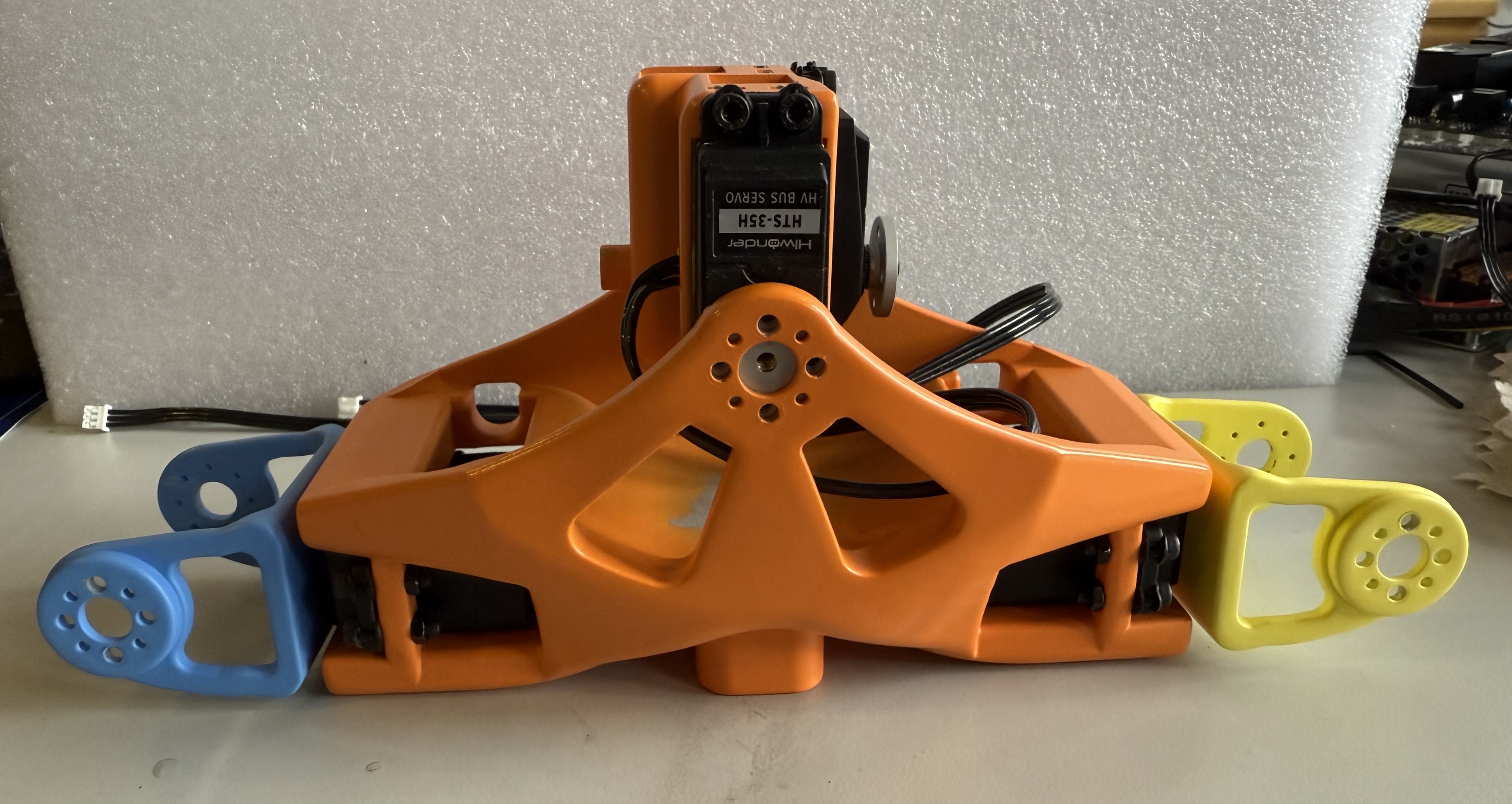
The two HiWonder HTS-35H servo are also part of this section of the assembly, and are used for the torso motors.
- Torso Bow motor
- Torso Tilt motor
All correlated motor IDs are listed above in Initializing Servo IDs and Positions, as well as instructions for how to set the IDs and their home positions. It is also recommended that you check the servo horn orientation during this time, following the alignment found in Servo Horn Alignment.
Chest Assembly
The chest will require:
- A P1 philips screwdriver
- A M2.5 allen key
- 12x black rubber spacers from the motor package
- 12x silver servo horn M3 screws
- 3x JST cables
- 12x M3 x 16 mm hex screws
- 8x M3 hex nuts
- 4x M3 square nuts
- Motor ID 4
- Motor ID 8
- the Shoulder Connector pieces
- the Chest piece
As recommended in the assembly notes, it is best to pre-thread the screw holes on the 3D printed parts. You should also have already Initialized the motor IDs and home positions with attached servo horns as described in the initialization instructions
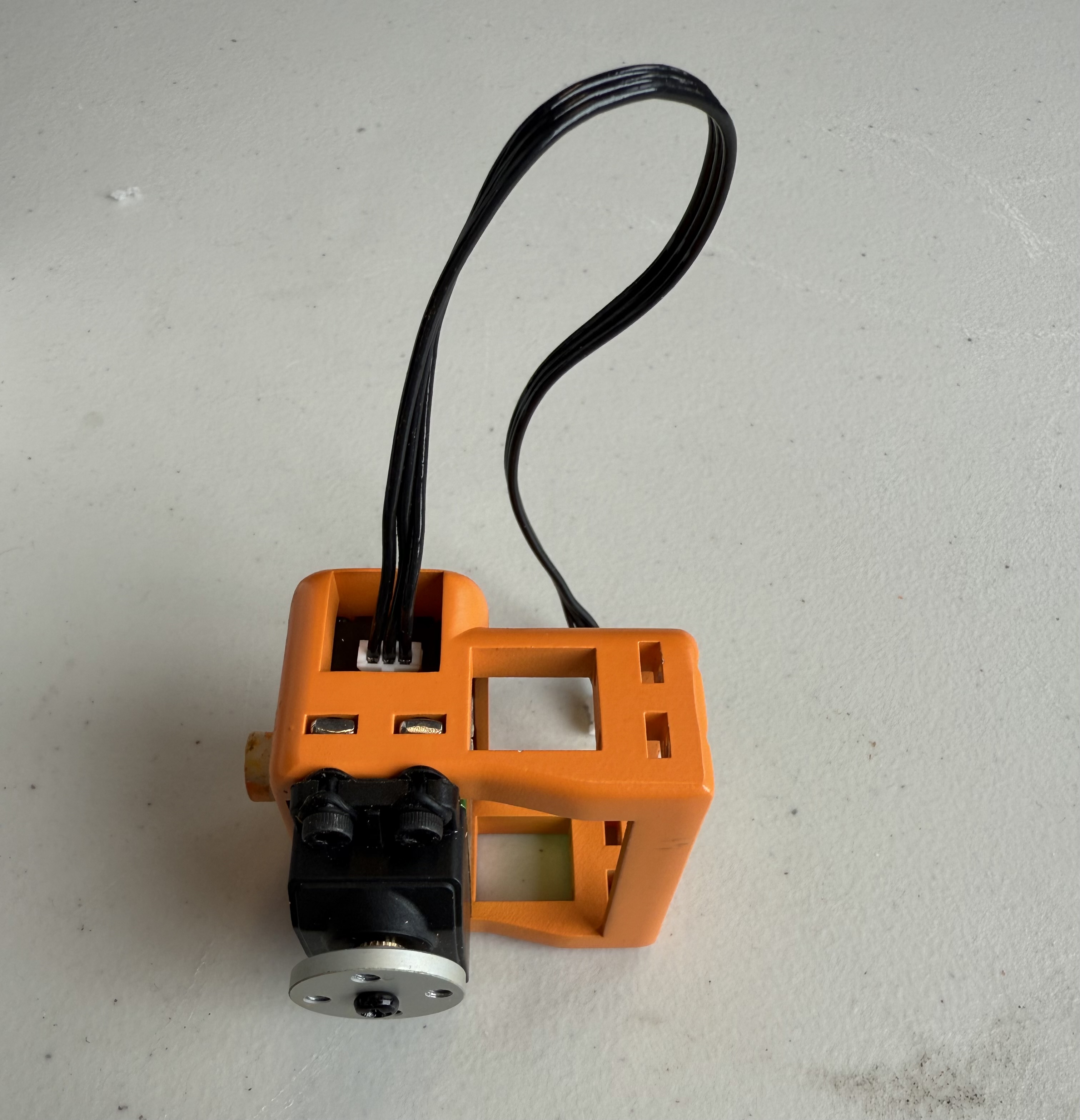
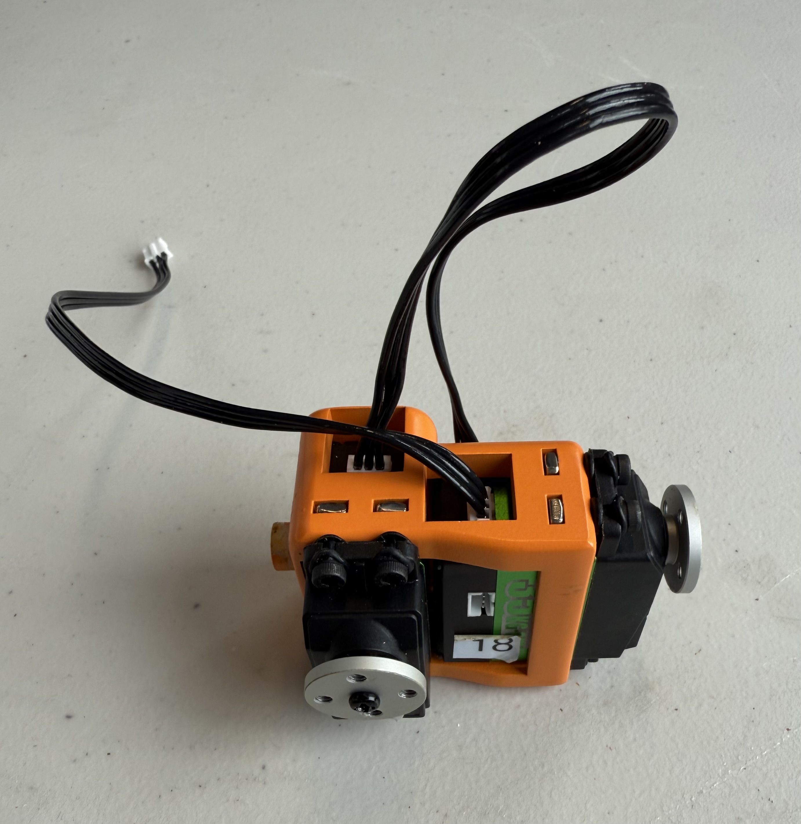
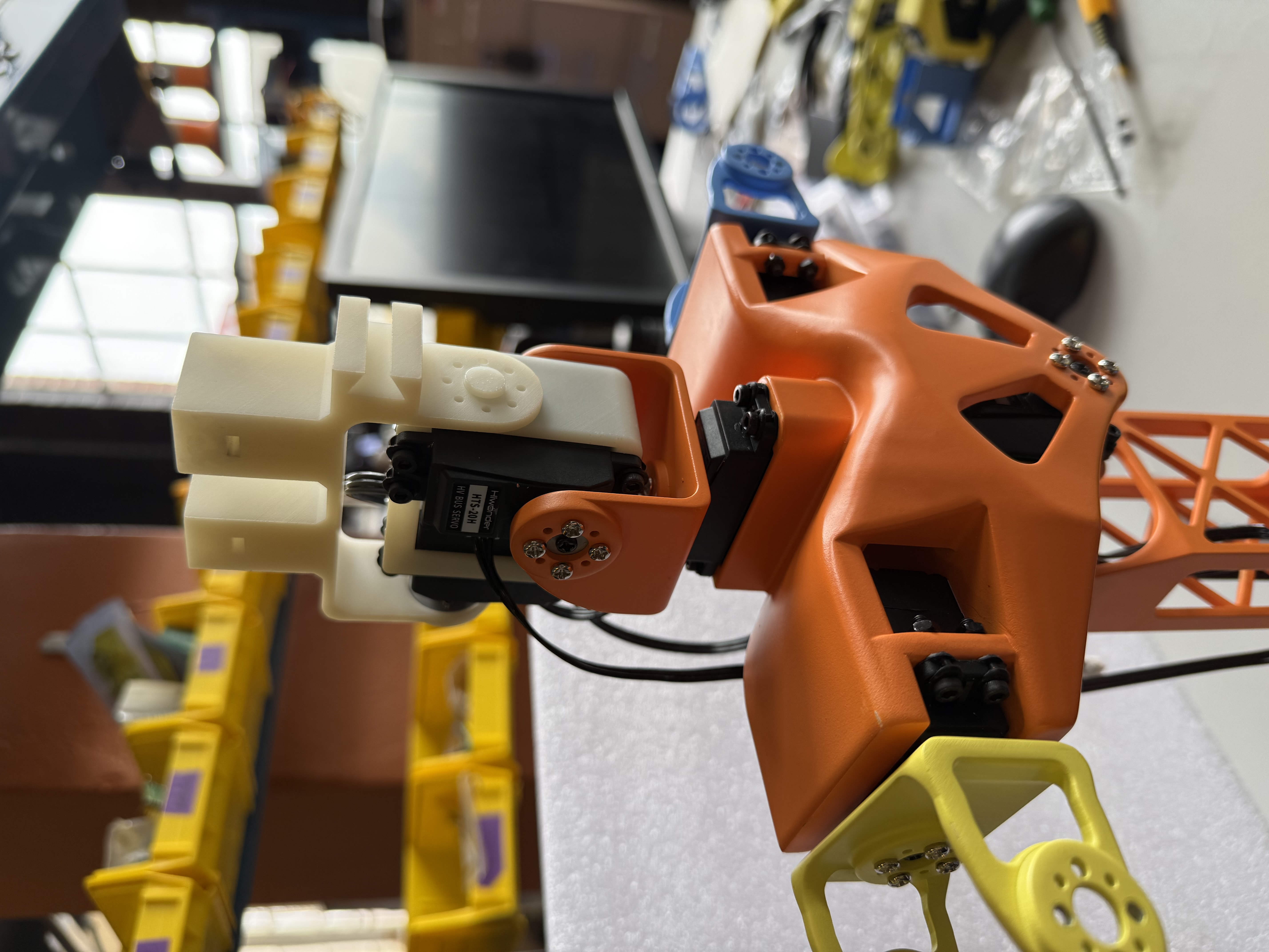
Right Shoulder Chest
- Insert the black rubber spacers into the screw slots for each of motor 4.
-
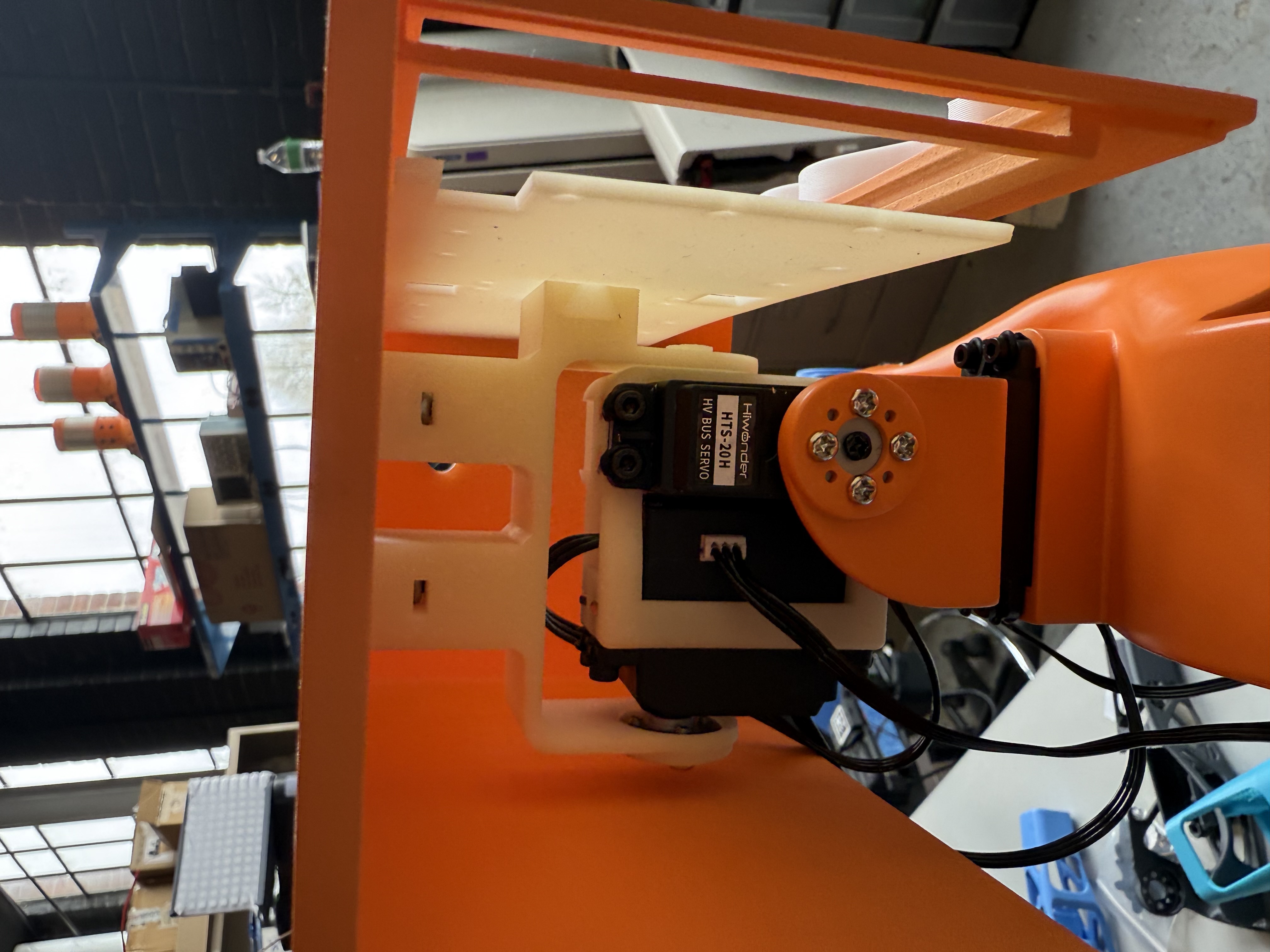
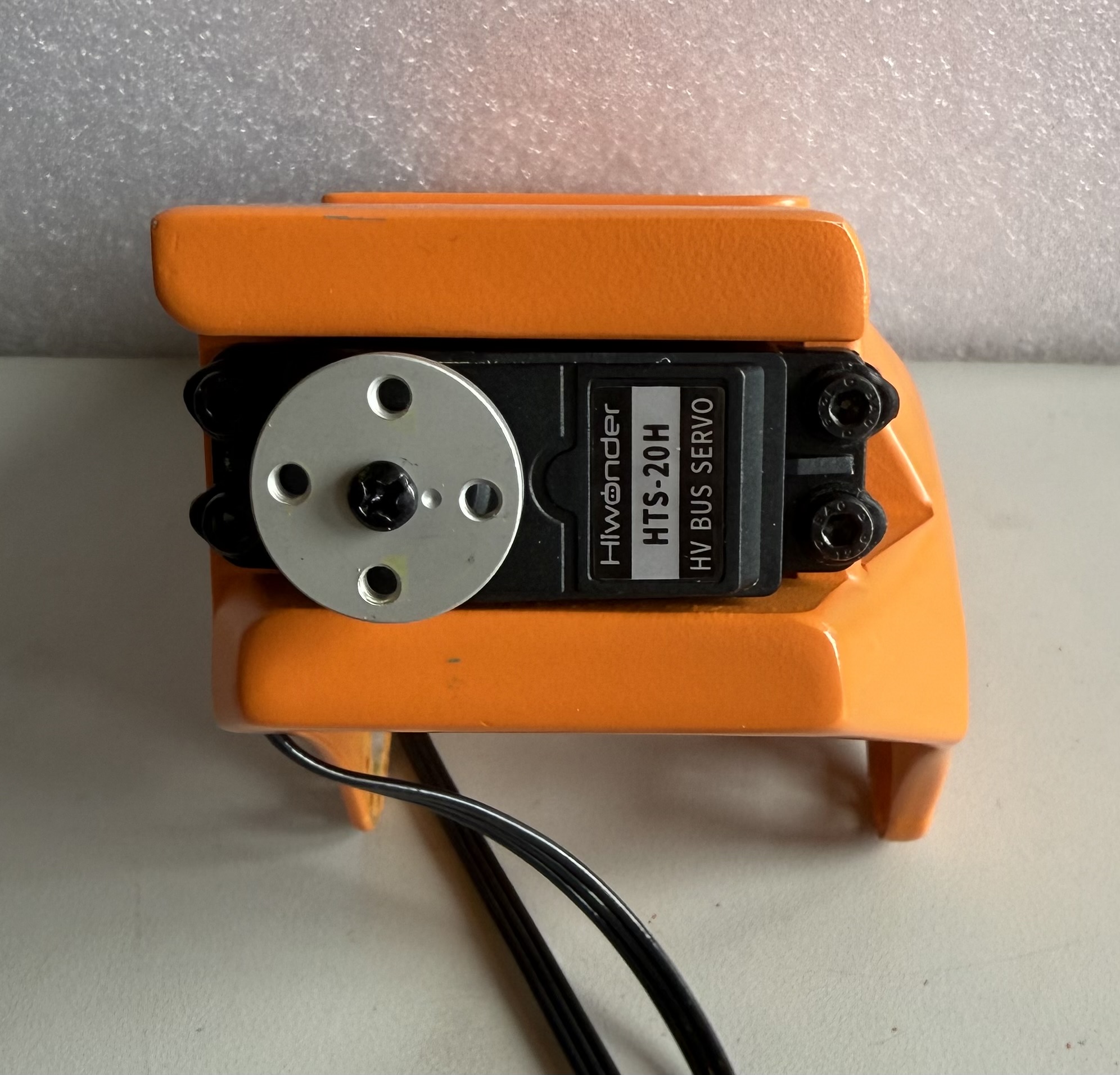
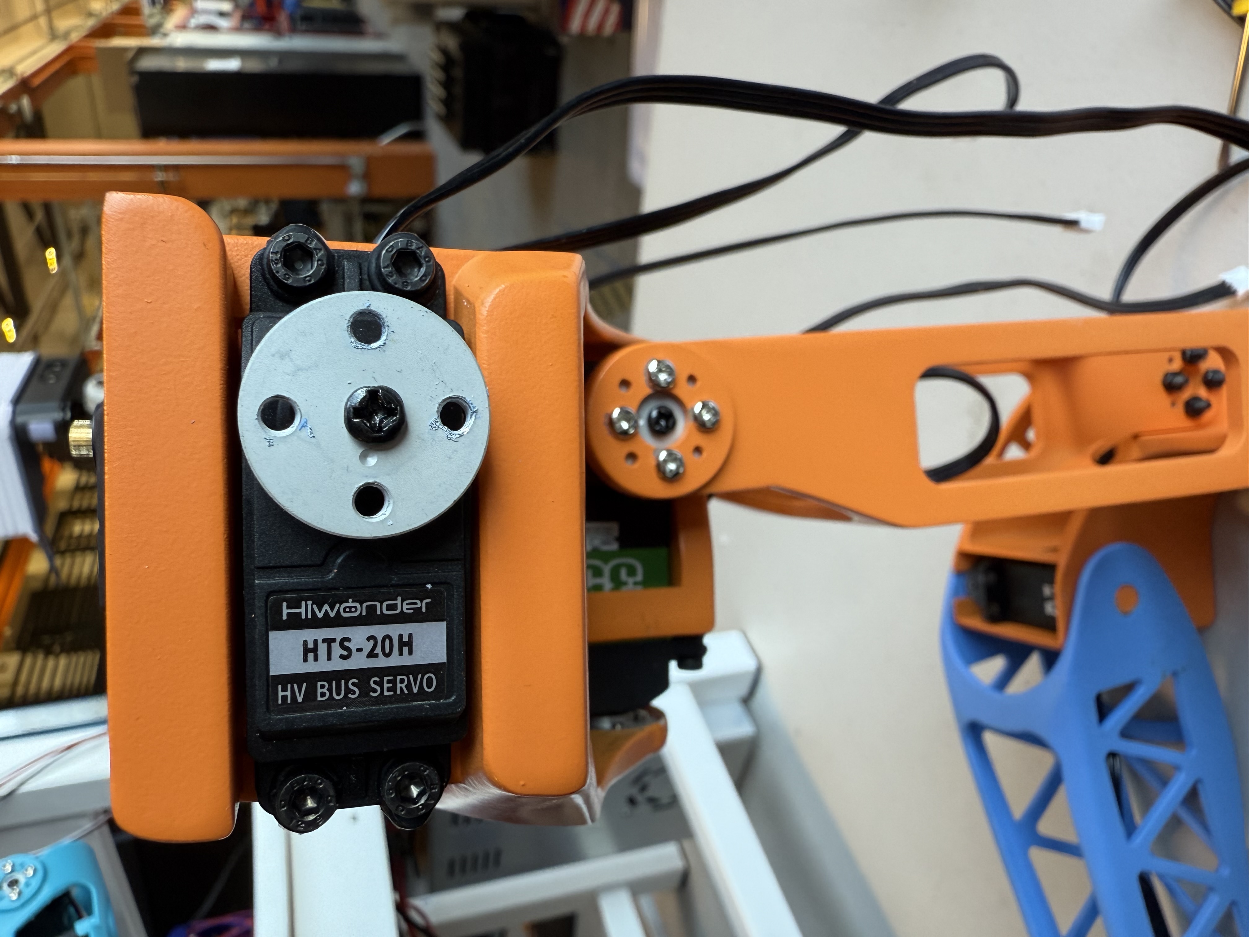
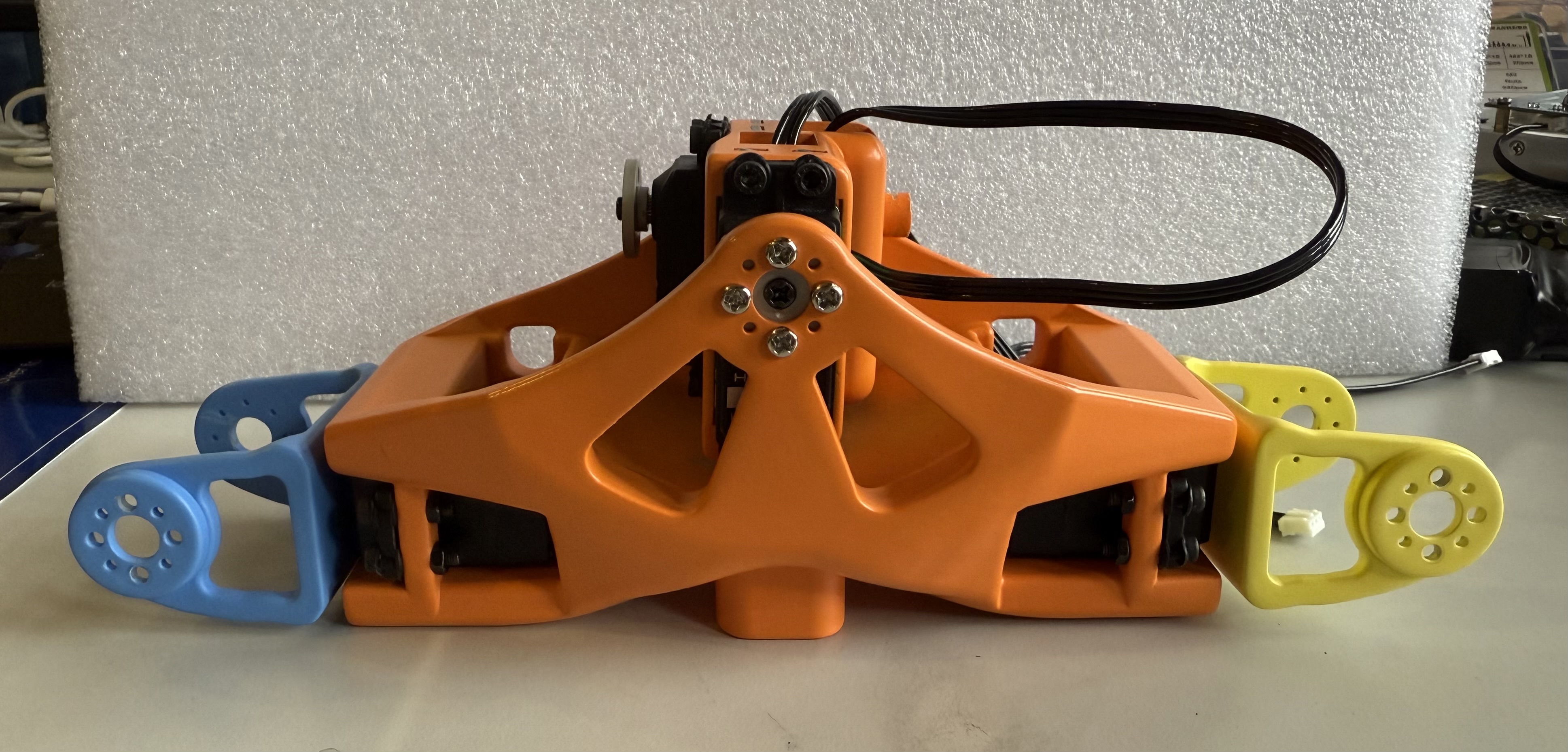
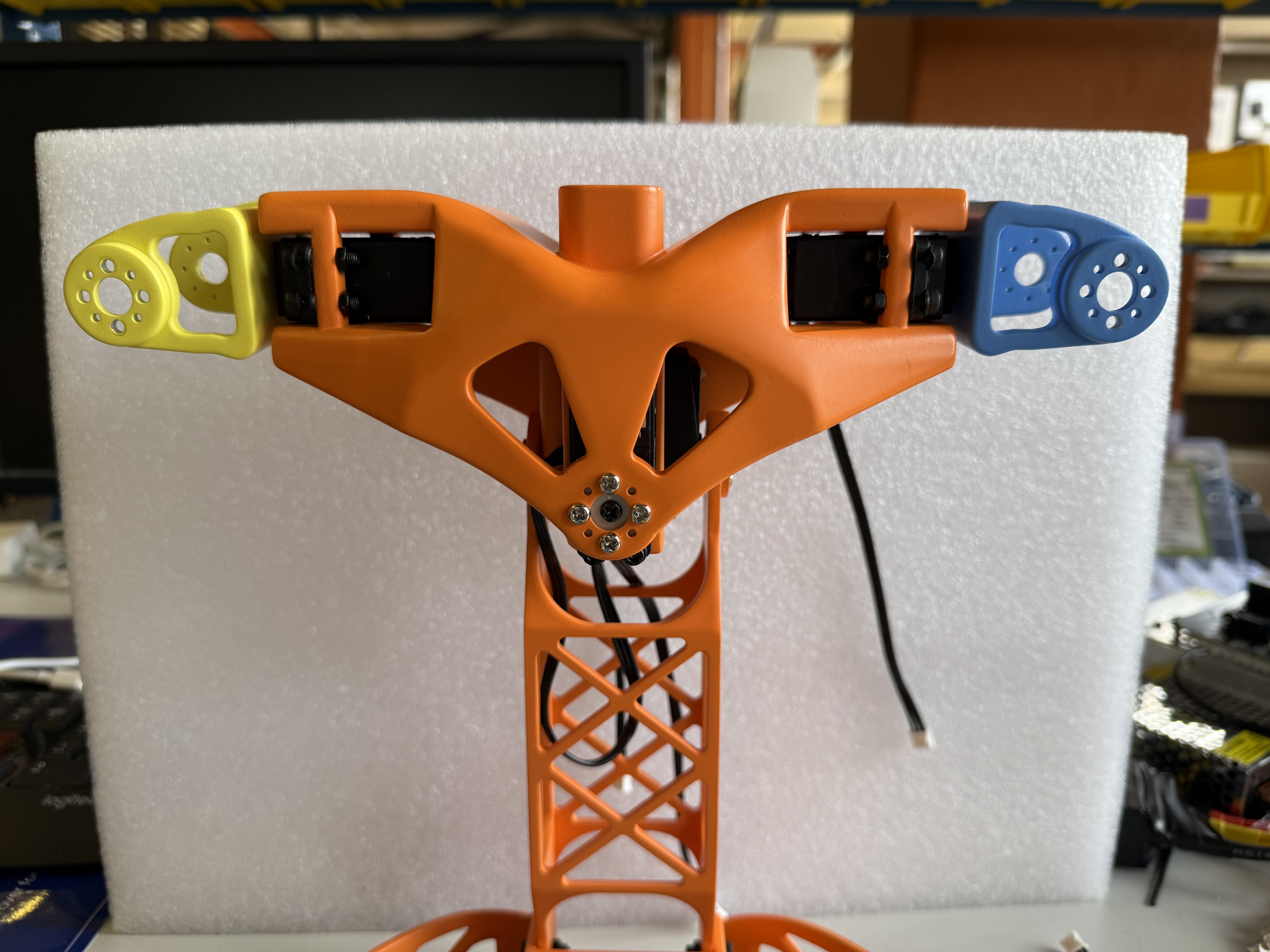
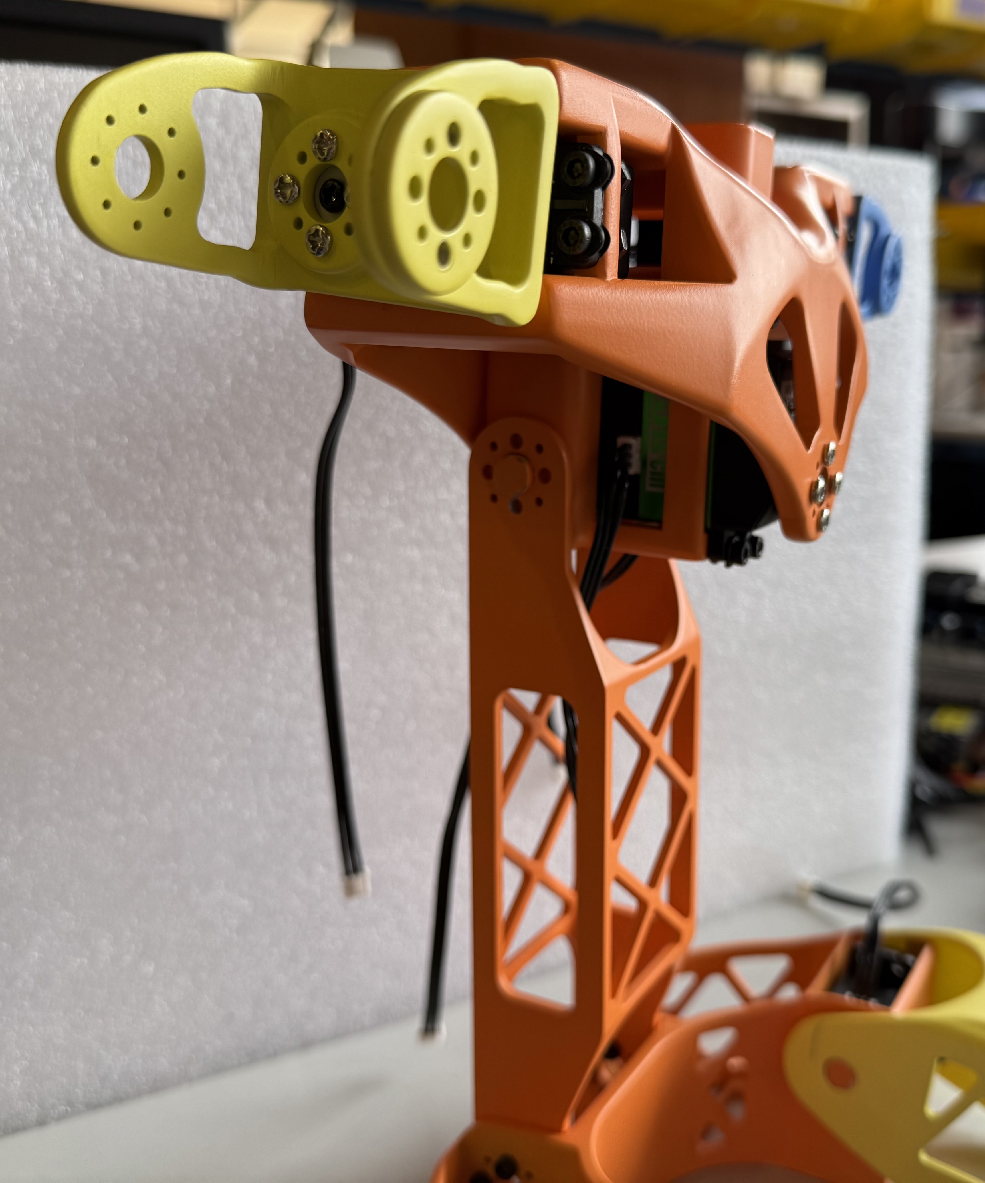
Insert motor 4 into the right shoulder slot on the chest piece. The servo should be oriented so the servo horn is closer to the back of the chest rather than the front as seen in the side photo below. Note the location of the dimple on the servo horn.
- Use 4 of the M3x16 screws and 4 of the hex nuts to screw motor 4 to the chest.
-
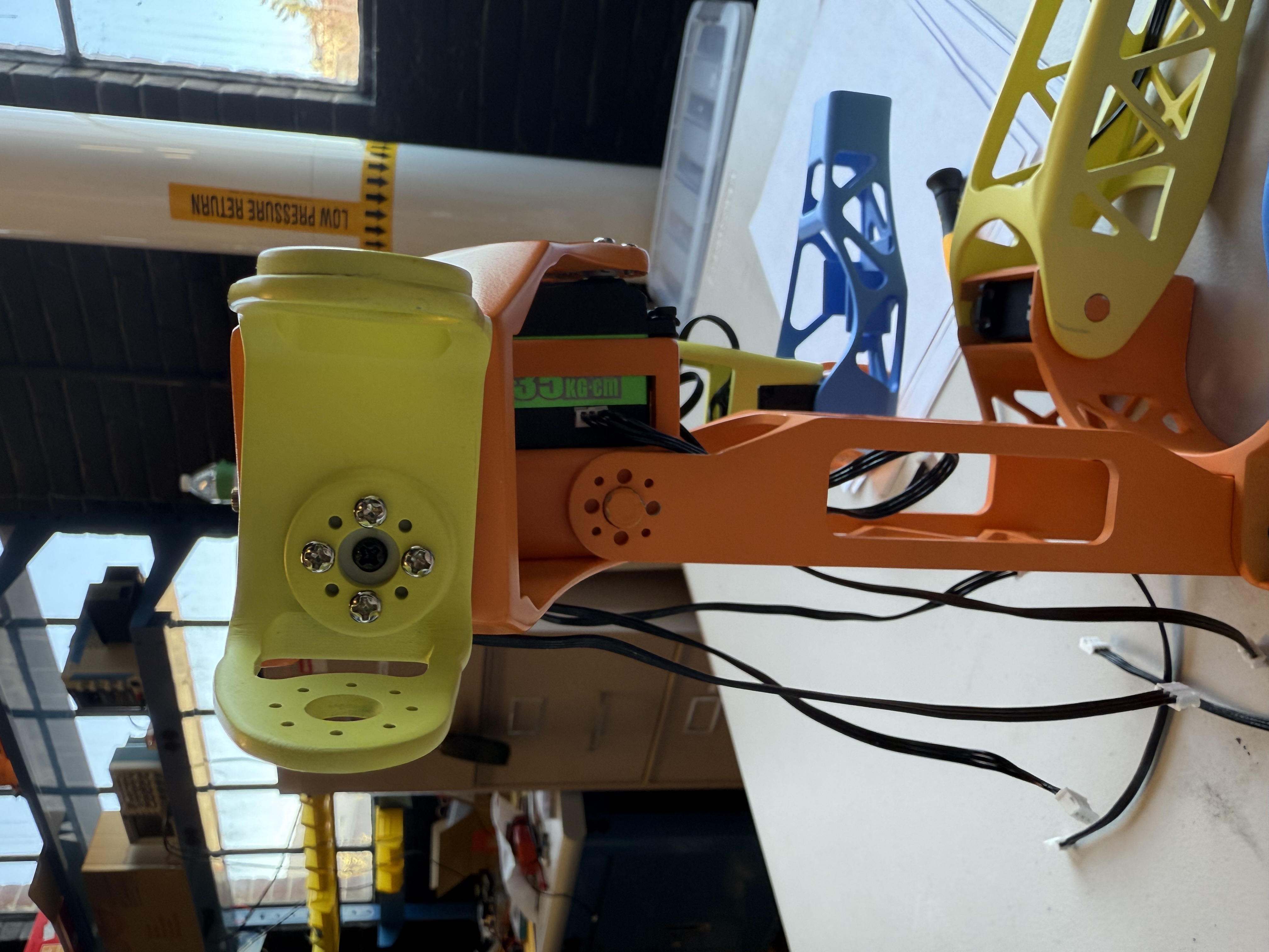
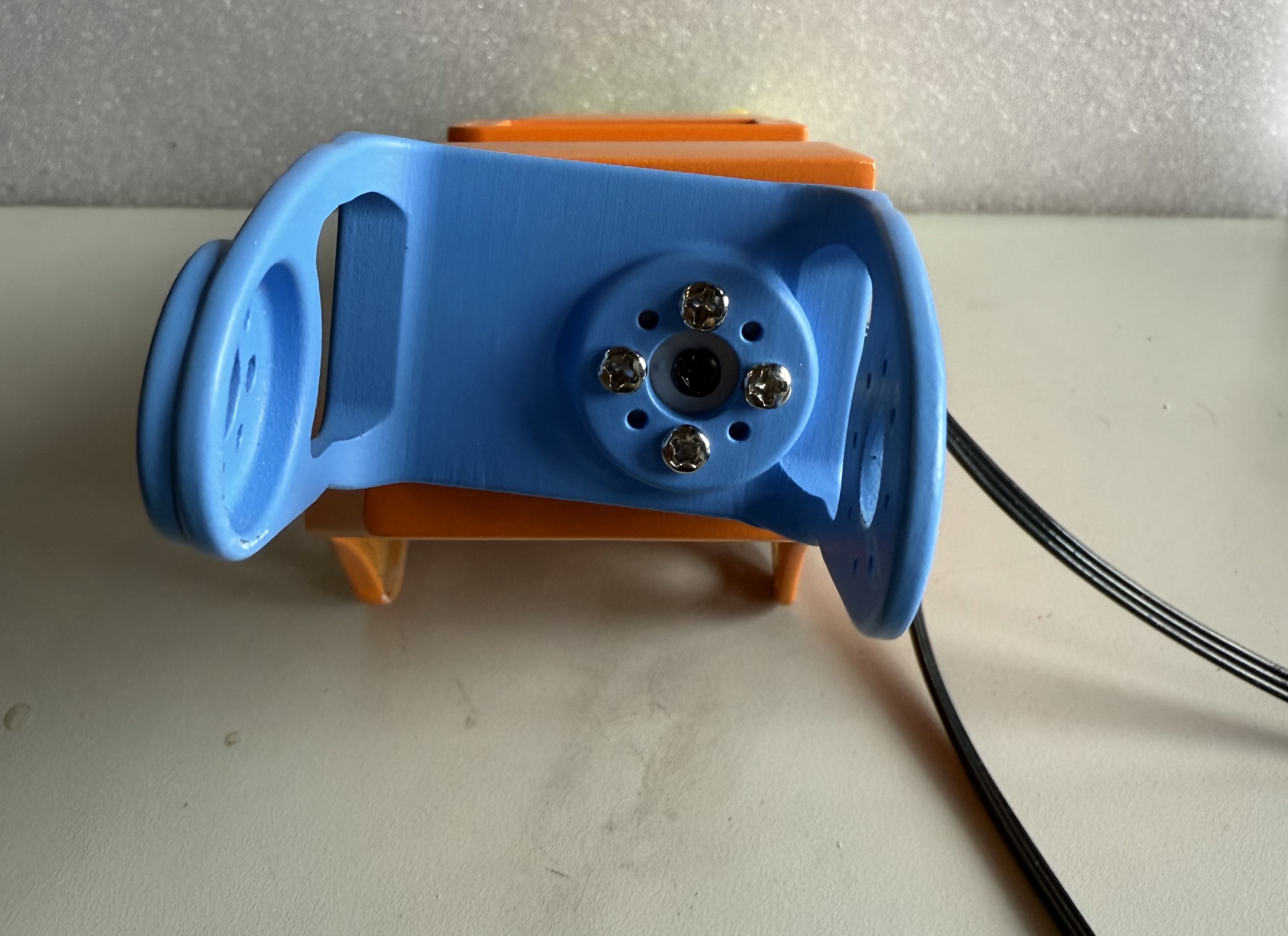
Use 4 of the silver M3 screws to attach motor 4’s servo horn to the righst side Shoulder Connector piece. It should be attached to the horn mount in the middle of the part, and the two sides of the part should be dipping “down” when attached as shown below.
- Attach the JST cable to the jst connector on the motor facing the back of the chest piece.
Left Shoulder Chest
- Insert the black rubber spacers into the screw slots for each of motor 8
-
Insert motor 8 into the left shoulder slot on the chest piece. The servo should be oriented so the servo horn is closer to the back of the chest rather than the front.
- Use 4 of the M3x16 screws and 4 of the M3 hex nuts to screw motor 8 to the chest.
-
Use 4 of the silver M3 screws to attach motor 4’s servo horn to the right side Shoulder Connector piece. It should be attached to the horn mount in the middle of the part, and the two sides of the part should be dipping “down” when attached as shown below.
- Attach the JST cable to the JST connector on the motor facing the back of the chest piece.
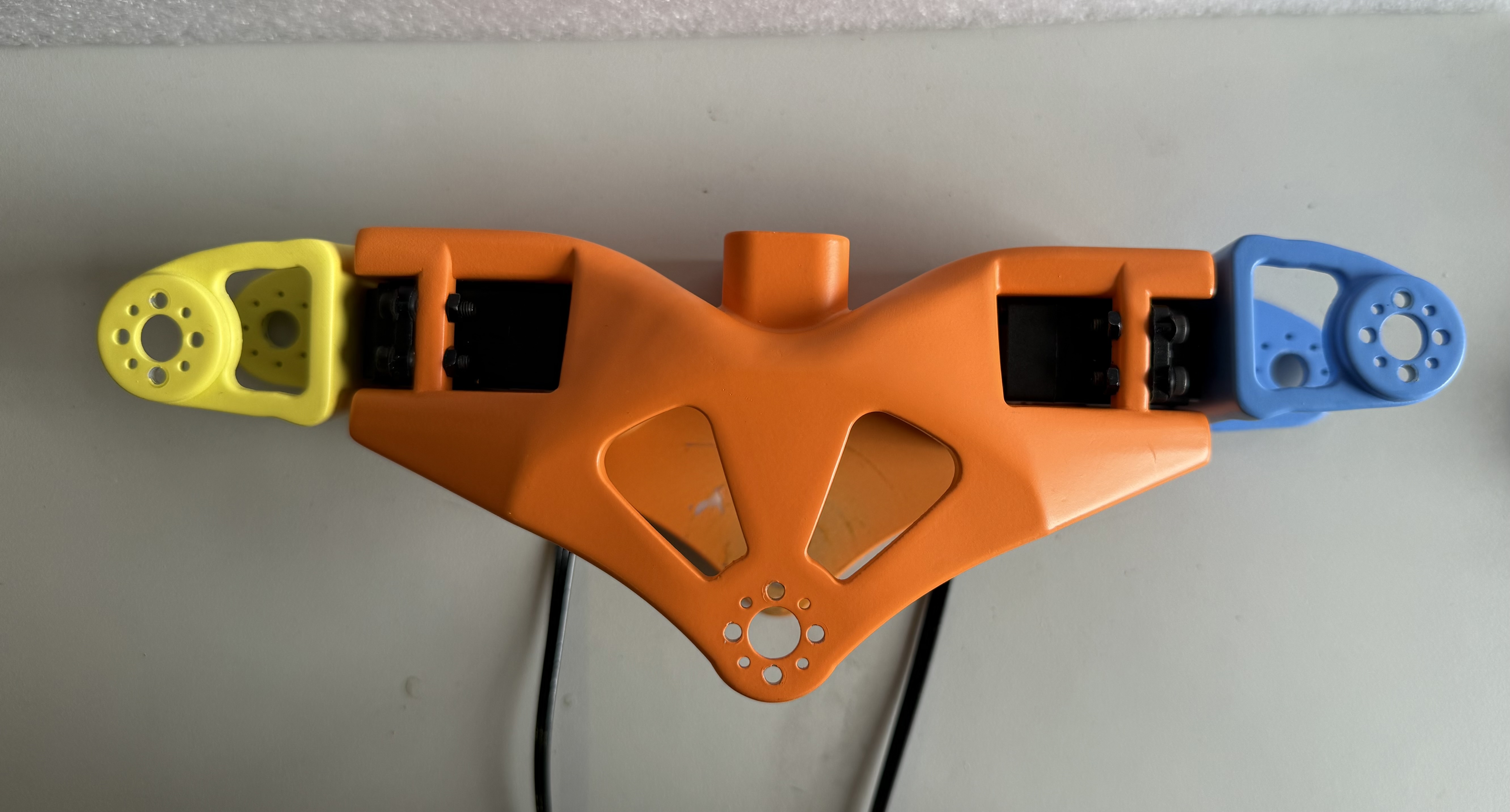
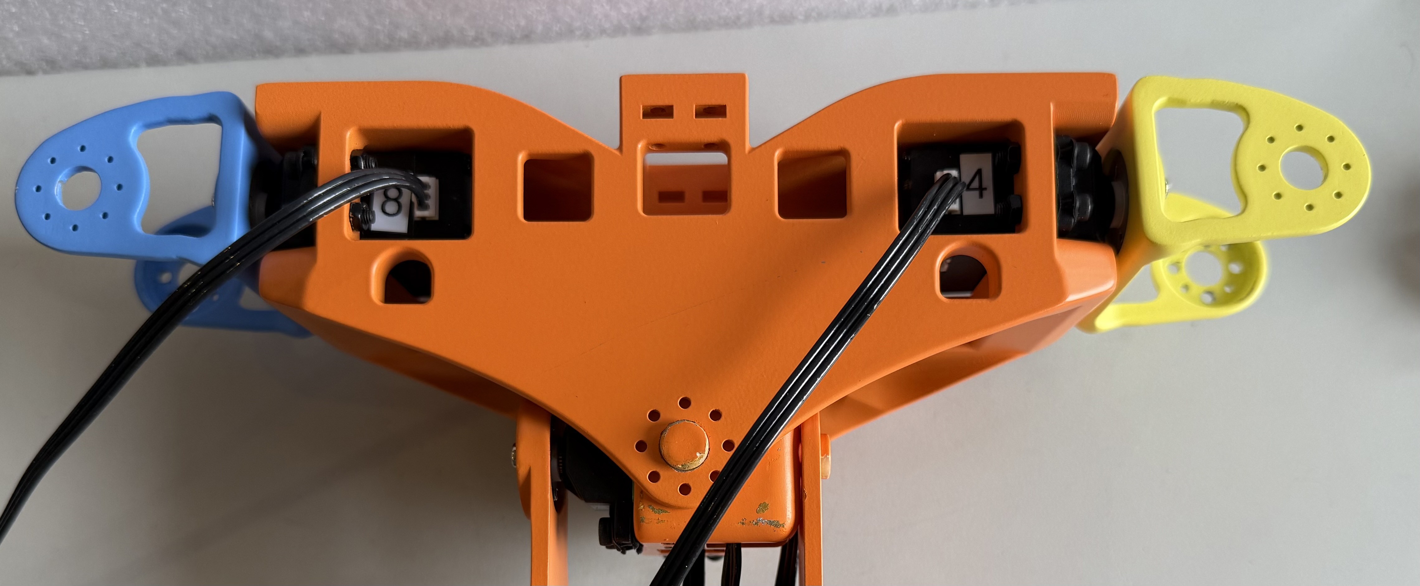
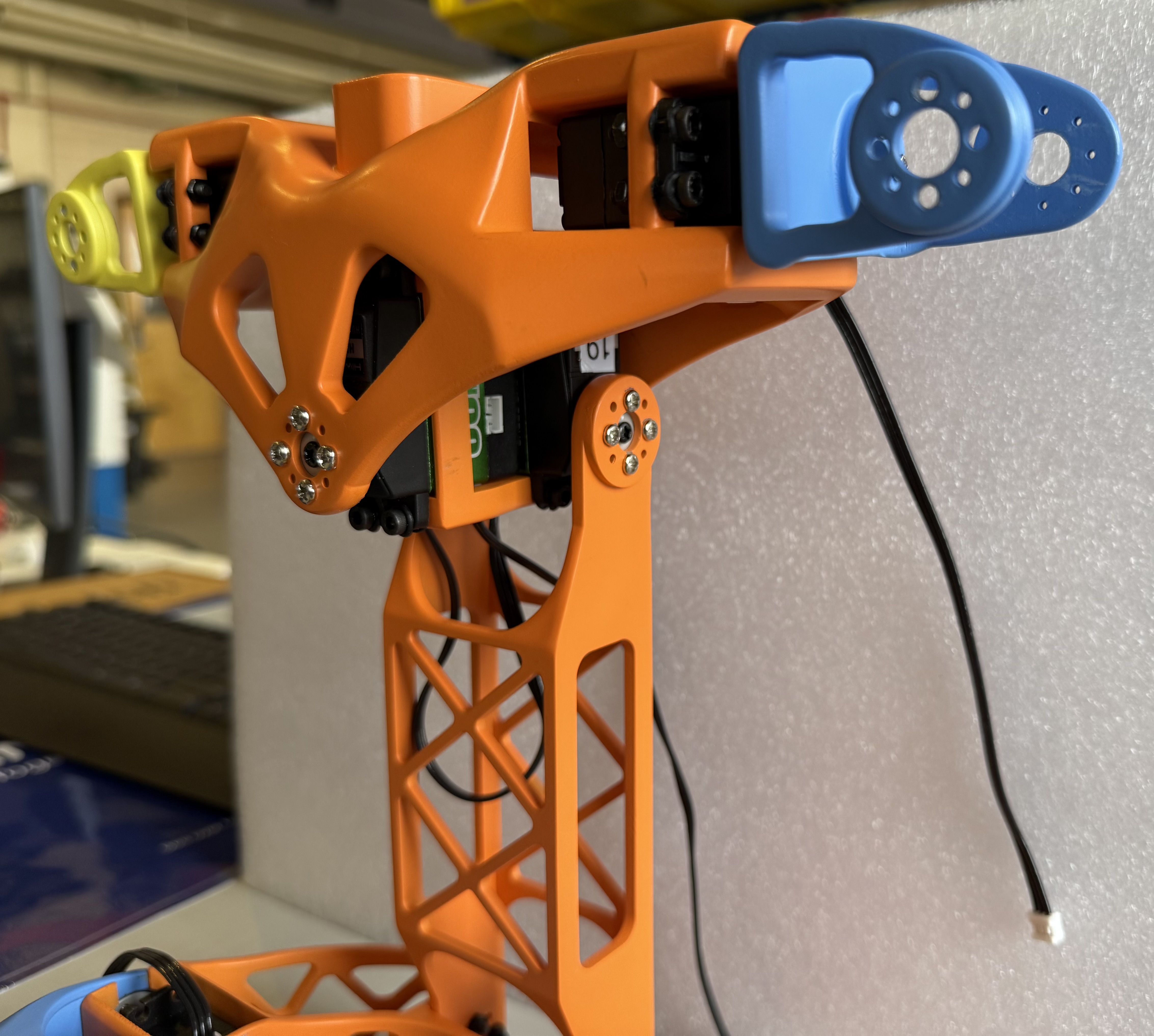
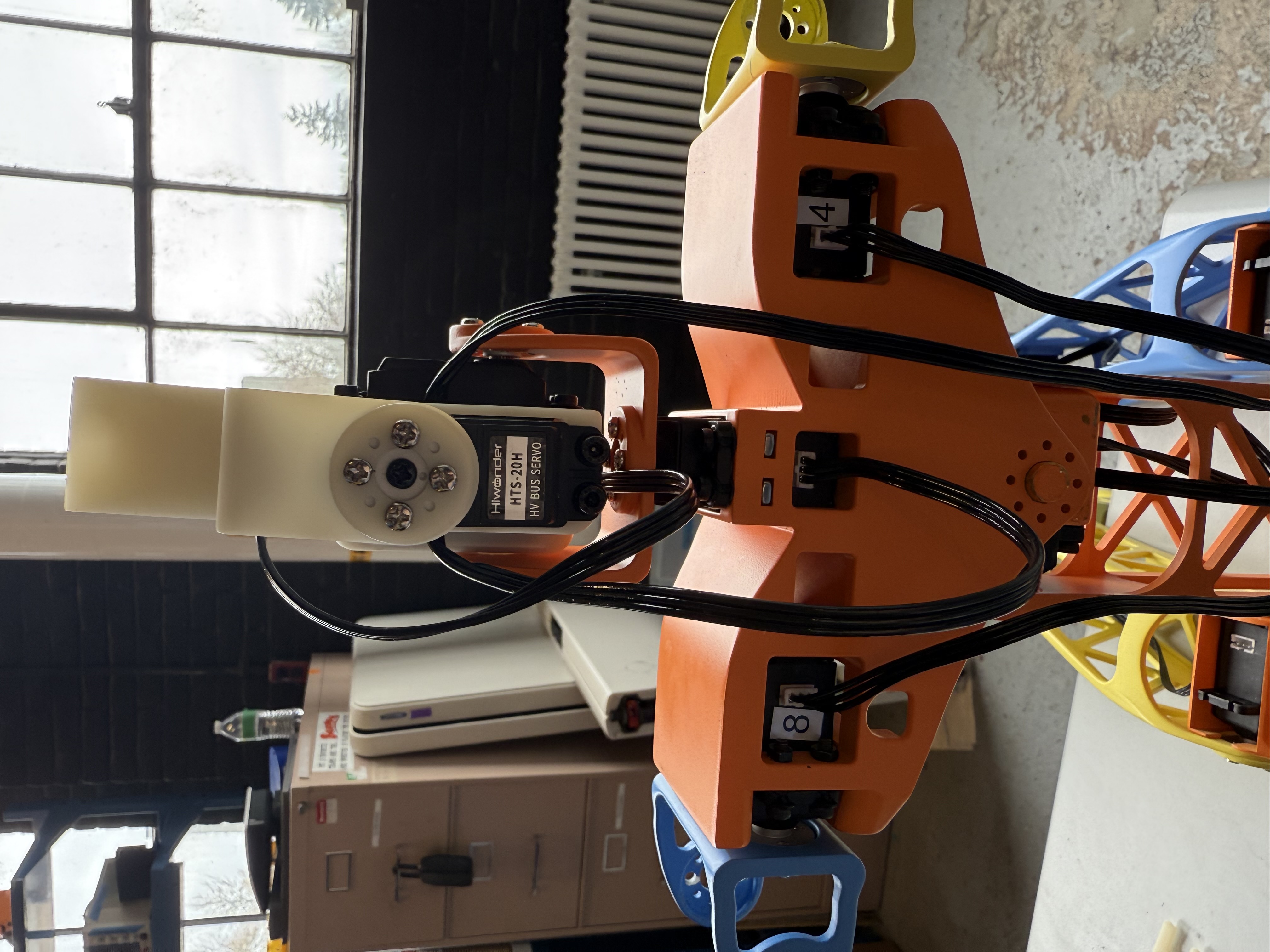
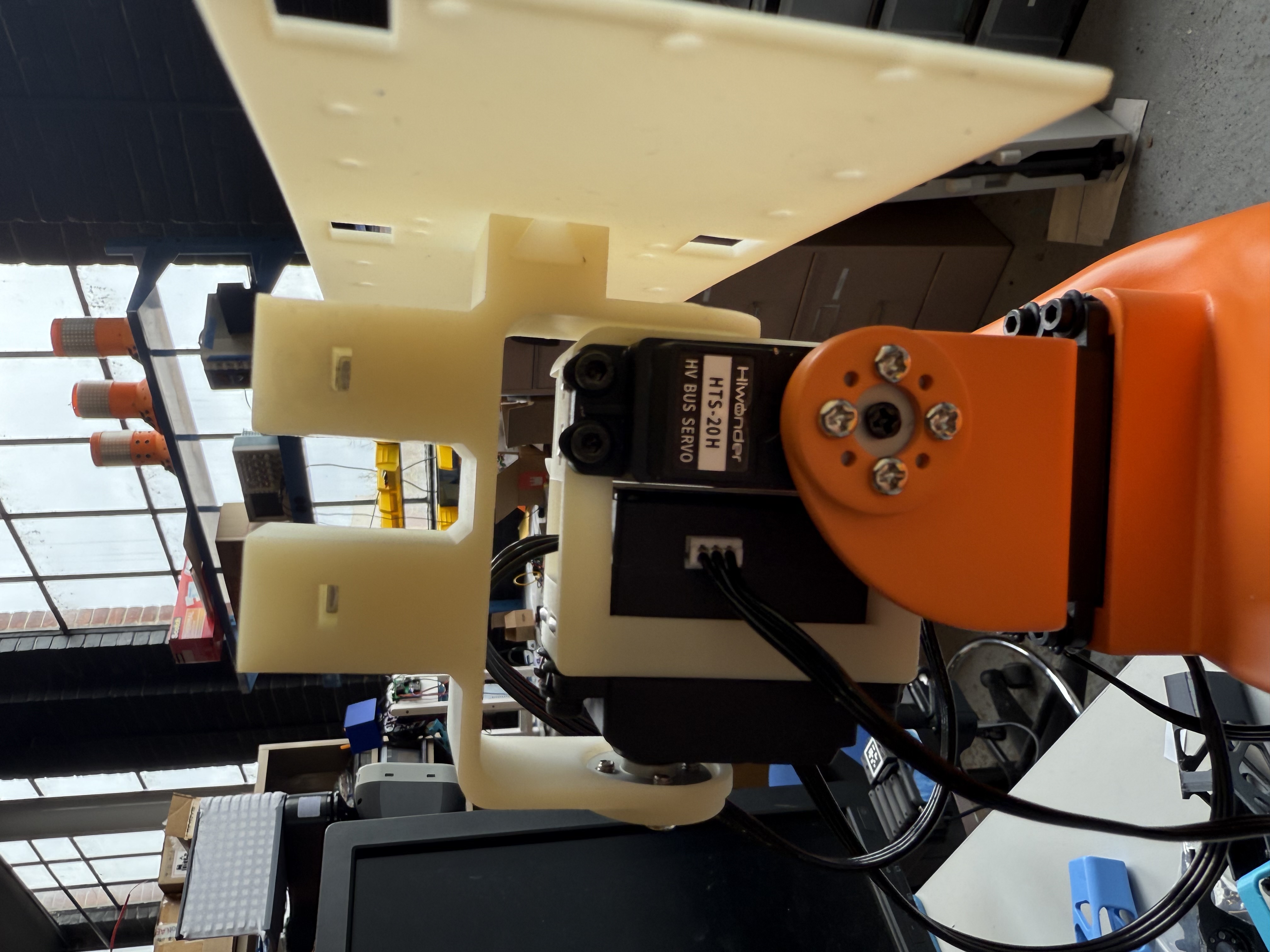
With both motors installed and JST cables connected, the chest from behind should look like
Chest Connector Assembly
The Chest Connector assembly will require:
- a M3 hex screwdriver
- 8x rubber spacers from the motor packages
- 2x black M3 screws from the motor packages
- 8x square M3 nuts
- 8x M3 x 16 mm hex screws
- 2x servo horns
- 8x servo horn M3 screws
- 2x JST cables
- Motor ID 19
- Motor ID 18
As recommended with every step, it is best to pre-thread the screw holes on the 3D printed parts.
Chest Bow
-
Insert the black rubber spacers into all four of the screw slots on motor 19
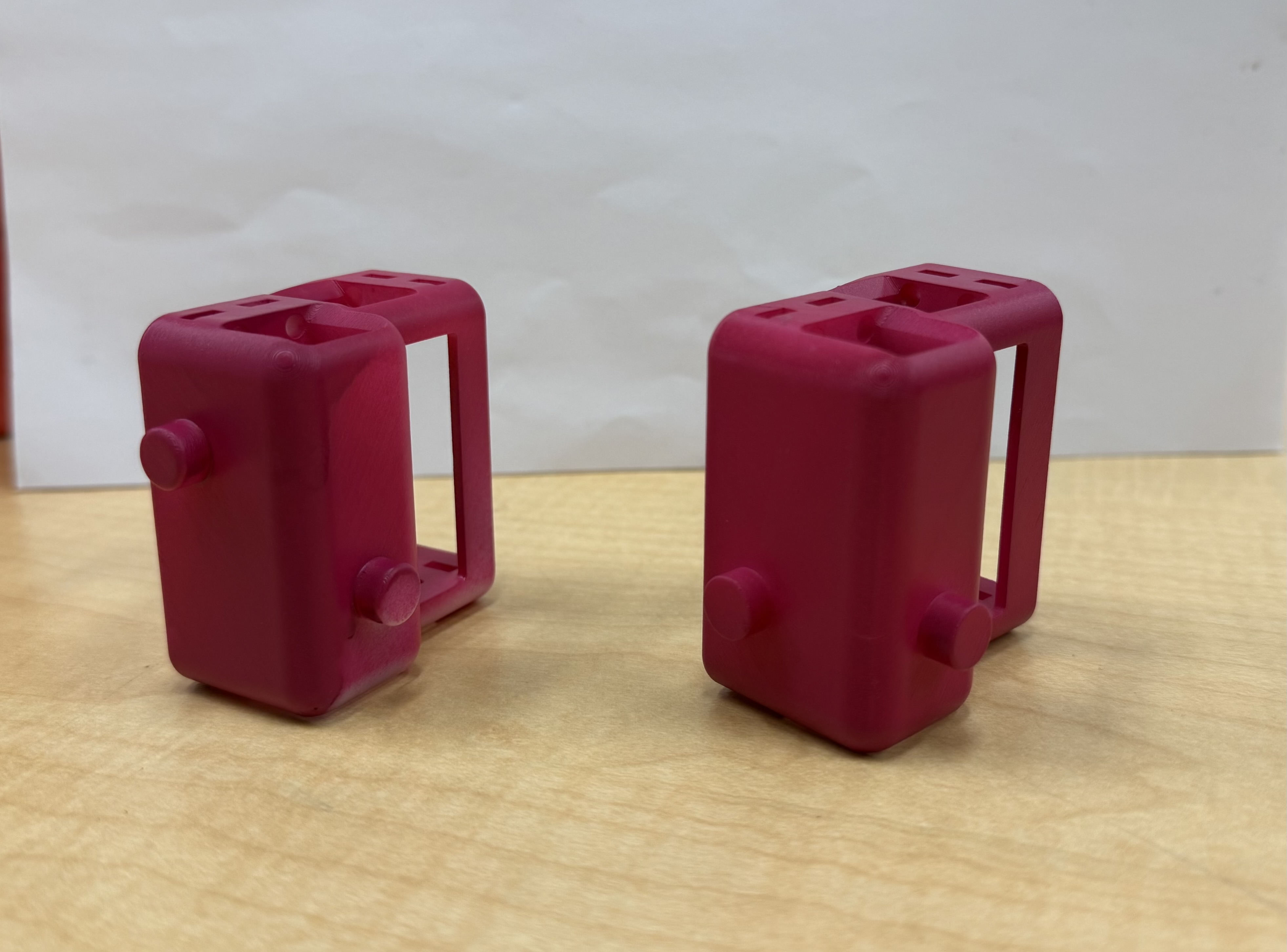 Use the connector on the right for Chest Assembly.
 -
Insert motor 19 into the slot that will not have another motor behind it. Make sure the servo horn and shaft are aligned to the plastic pin on the opposite side as shown in the image below.
-
Insert four of the M3 square nuts into the square nut slots around the motor and screw them down using the M3 x 16 mm screws.
Chest tilt
- Insert the black rubber spacers into all four of the screw slots on motor 18
-
Insert motor 18 into the remaining motor slot, making sure the servo horn and shaft are aligned to the plastic pin on the opposite side as shown below.
- Insert four of the M3 square nuts into the square nut slots around the motor and screw them down using the M3 x 16 mm screws.
Attaching to the Chest
-
Begin by slotting motor 18 into the chest upside down, with the servo horn facing the front plate, as shown below. Do not screw in the servo horn yet.

-
Rotate the chest connector assembly until it is right side up inside the chest, as shown below.
-
Attach the servo horn to the chest using four of the silver M3 motor screws.
Spine Assembly
The Spine assembly will require:
- a M3 hex screwdriver
- 4x silver servo horn M3 screws from the motor package
- 8x hex nuts
- 8x M3 x 14 mm hex screws
As recommended with every step, it is best to pre-thread the screw holes on the 3D printed parts.
- Attach bottom frame of spine to hips using 4 M3 x 14 mm screws and 4 hex nuts. Screw in diamond shape.
The figure below shows screw placement:
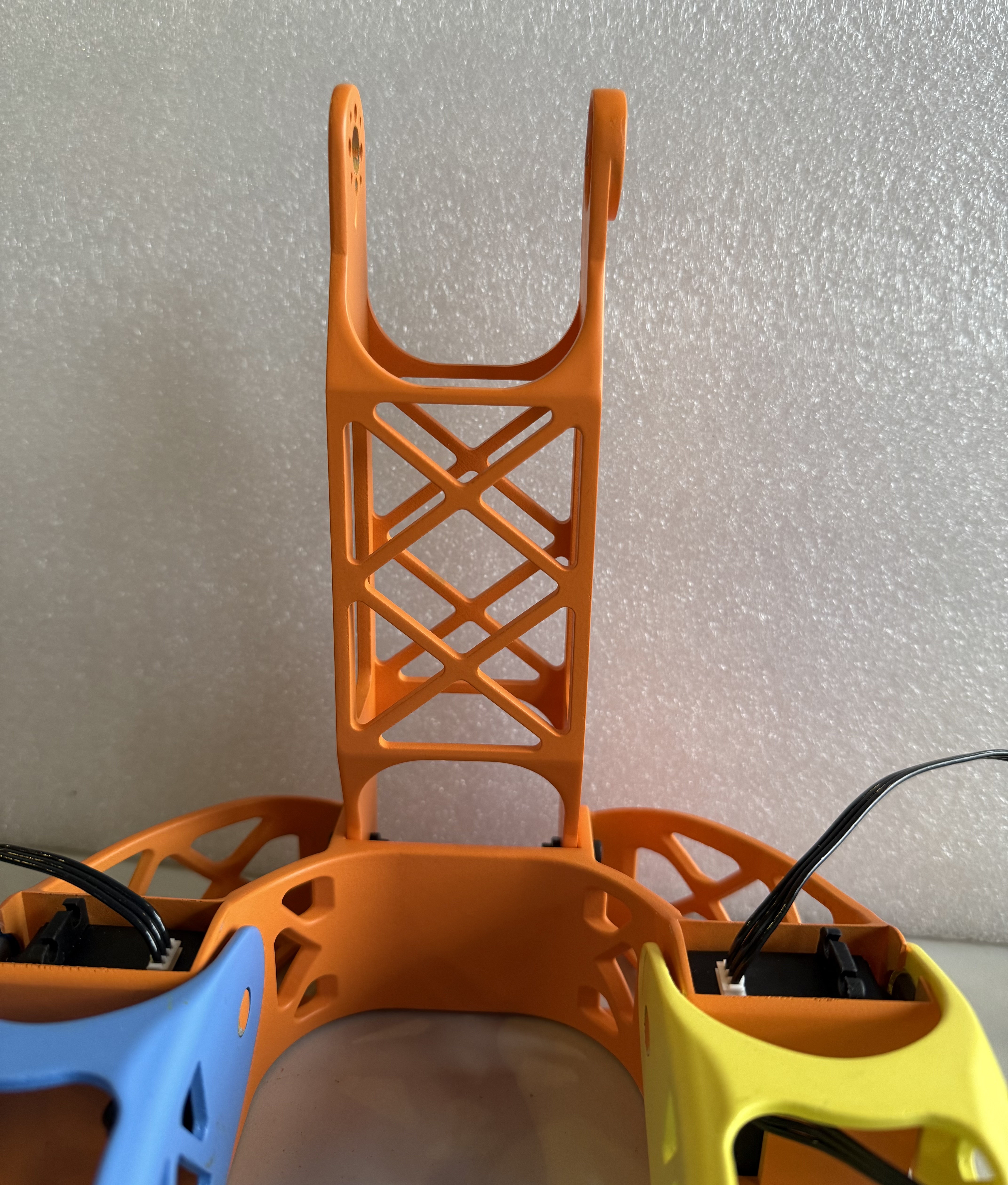
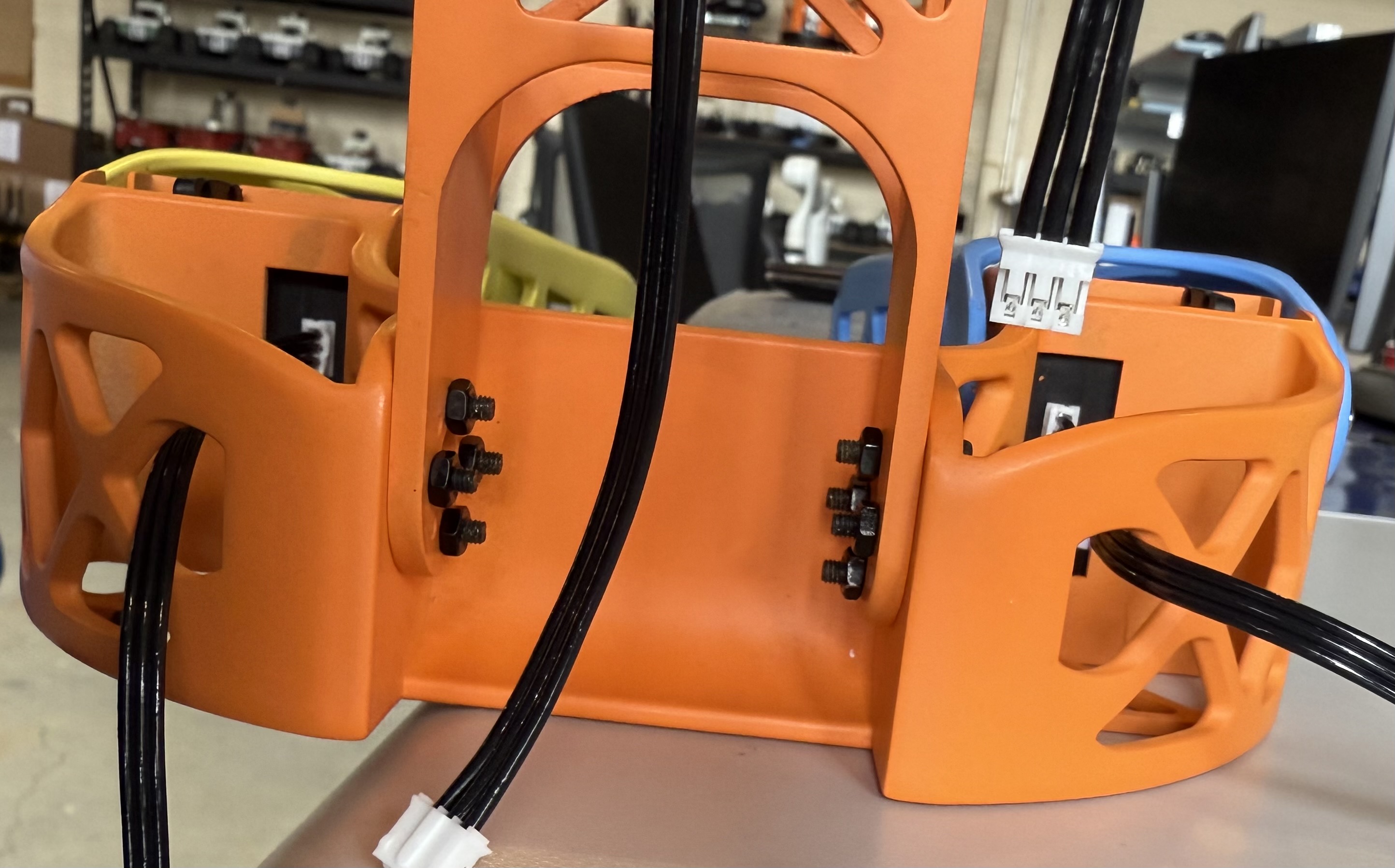
Following the attachment to the hips is attaching the Chest Assembly to the Spine. The final product should look like the figures below:
-
Slot the spine over motor 19, with the servo horn over the bulge, and the flat plane of the spine aligned with the back of the chest piece. The figure below is only meant to show correct orientation.
-
Screw in motor 19 by attaching four silver M3 motor screws to the servo horn through the holes in the spine.
Final product:
Neck Assembly
The neck will require:
- a M3 hex screwdriver
- 1 servo horn
- 1 black M3 screw from the motor package
- 4x black rubber spacers from the motor package
- 4x silver servo horn M3 screws
- 1 JST cable
- 4x M3 x 16 mm hex screws
- 4x M3 square nuts
- Motor ID 3
As recommended with every step, it is best to pre-thread the screw holes on the 3D printed parts.
- Insert the black rubber spacers into the screw slots for each of motor 3
-
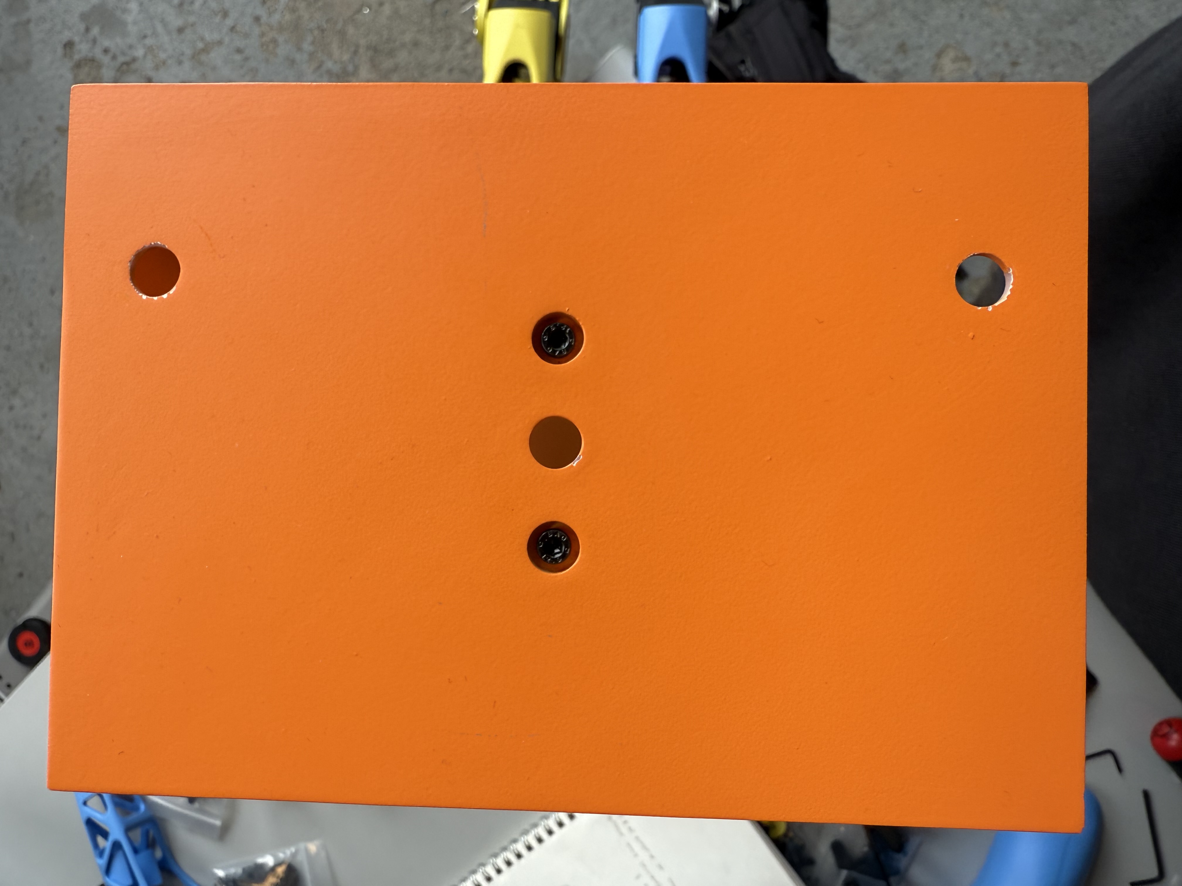
Insert 2 of the M3 square nuts into the slots in on the inside of the neck of the chest piece, as shown below.
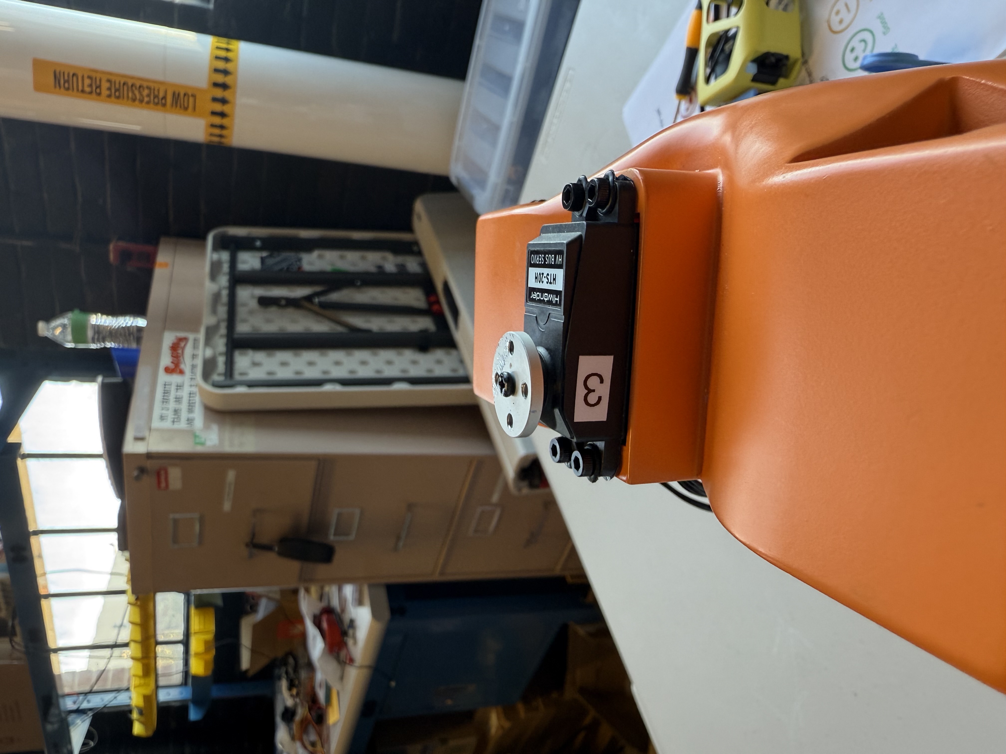
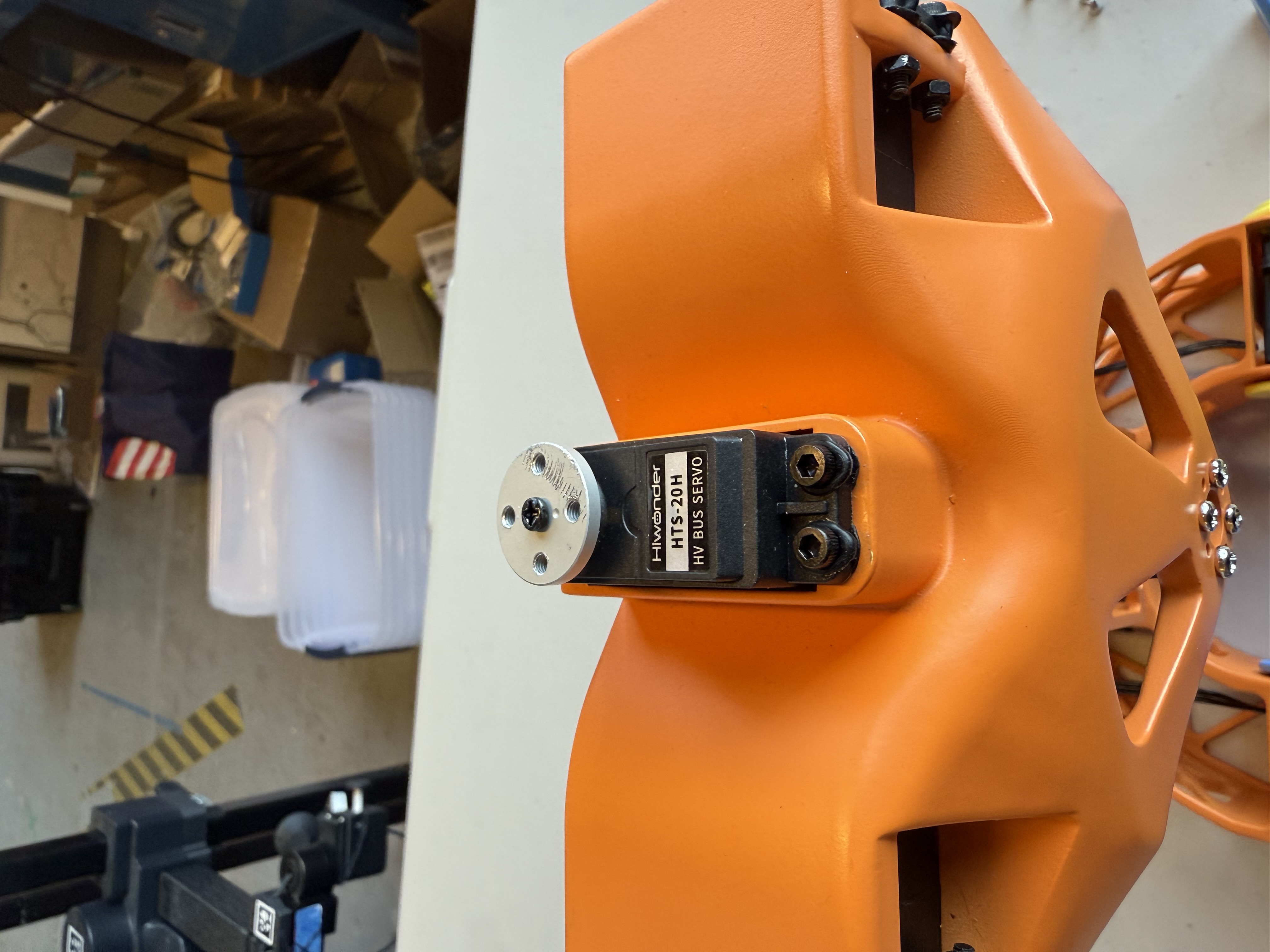
- Insert motor 3 into the neck of the chest piece. The servo should be oriented so the servo horn is closer to the back of the chest rather than the front.
- Insert the remaining 2 M3 square nuts into the slots on the back of the neck of the chest piece.
-
Use the remaining 4 M3x16 hex screws to screw down motor 3 to the chest, making sure to screw into the square nuts.
-
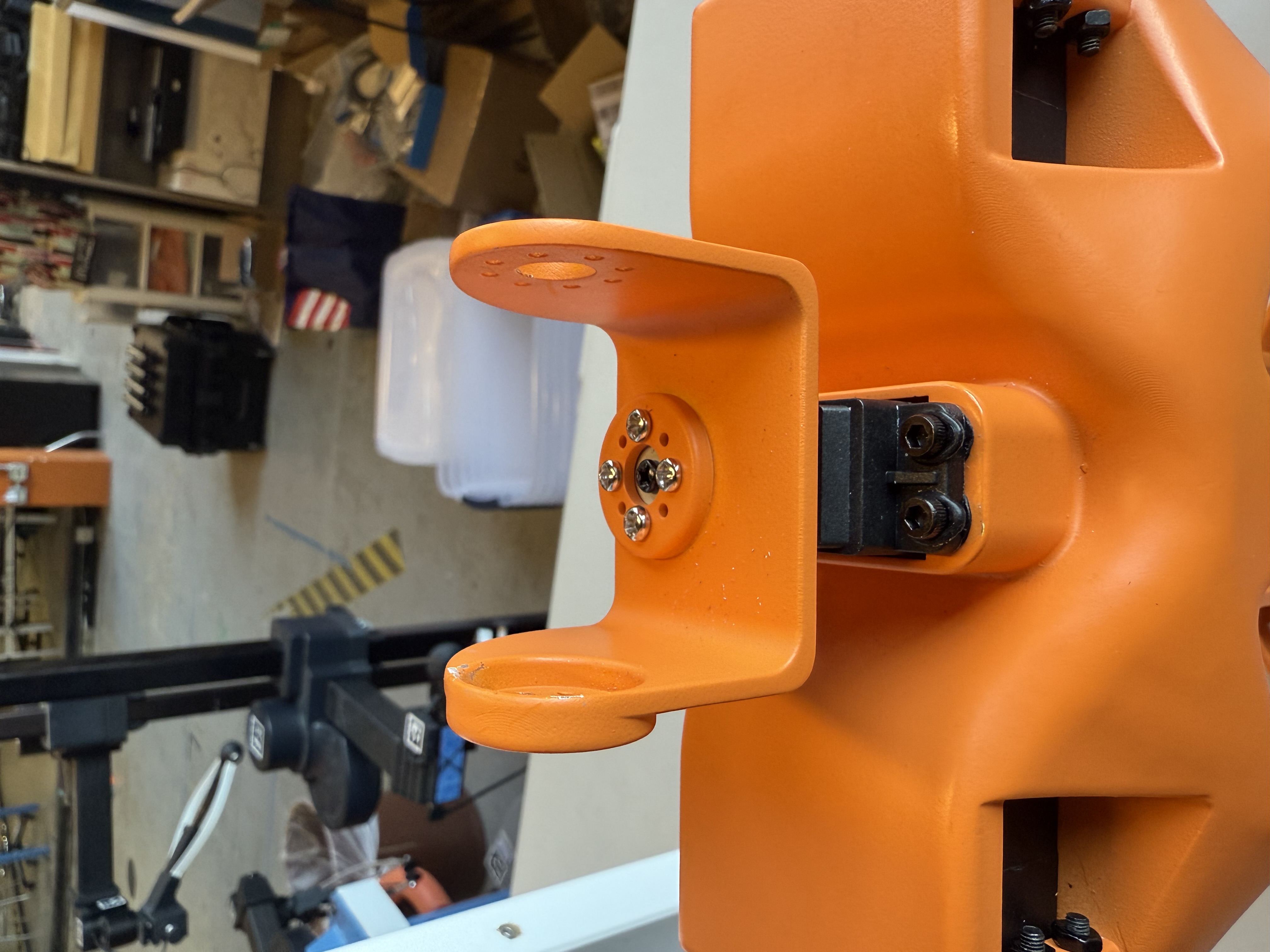
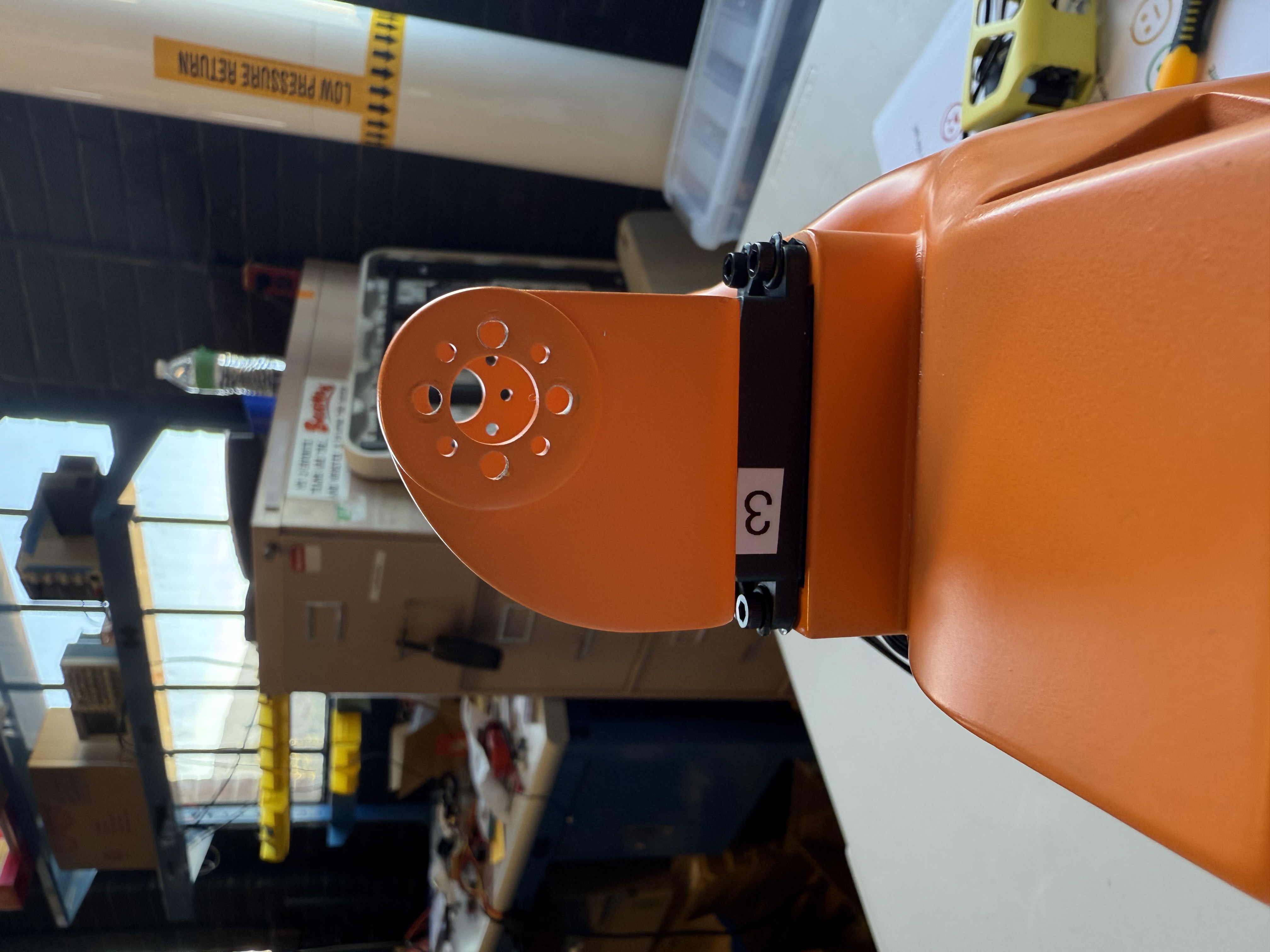
Attach the neck piece to the servo horn with 4 silver M3 screws, matching the orientation shown below.
- Attach the JST cable to the jst connector on the motor facing the back of the chest piece.
Neck Connector Assembly
The Neck Connector will require:
- a M3 hex screwdriver
- 2x servo horns
- 8x servo horn M3 screws
- 2x black M3 screws from the motor packages
- 8x black rubber spacers from the motor packages
- 3x JST cables
- 8x M3 x 16 mm hex screws
- 8x square nuts
- Motor ID 2
- Motor ID 1
As recommended with every step, it is best to pre-thread the screw holes on the 3D printed parts.
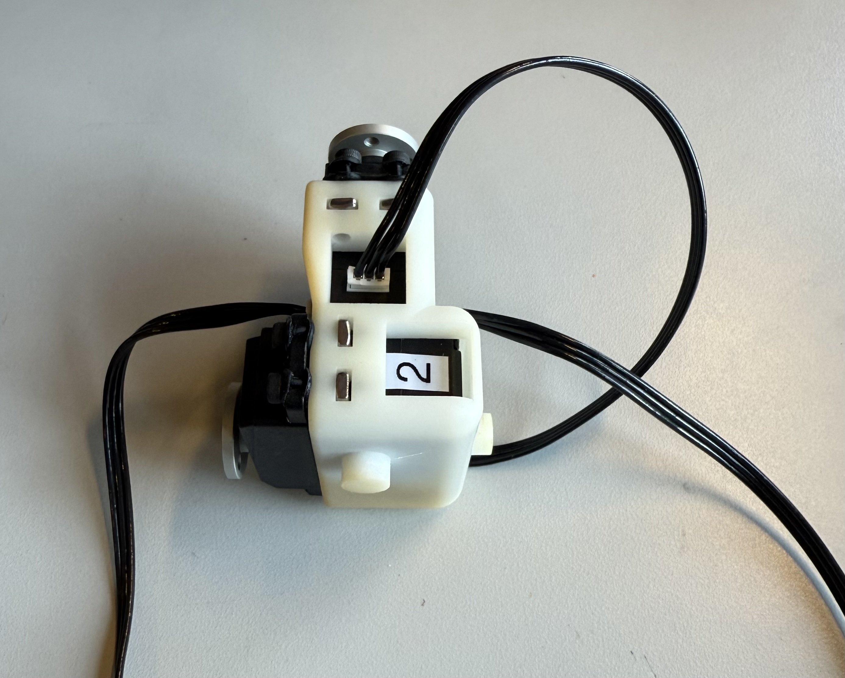
Neck Bow
-
Insert the black rubber spacers into all four of the screw slots on motor 2
Use the connector on the left for Neck Assembly. -
Insert motor 2 into the slot that will not have another motor behind it. Make sure the servo horn and shaft are aligned to the plastic pin on the opposite side as shown in the image below.
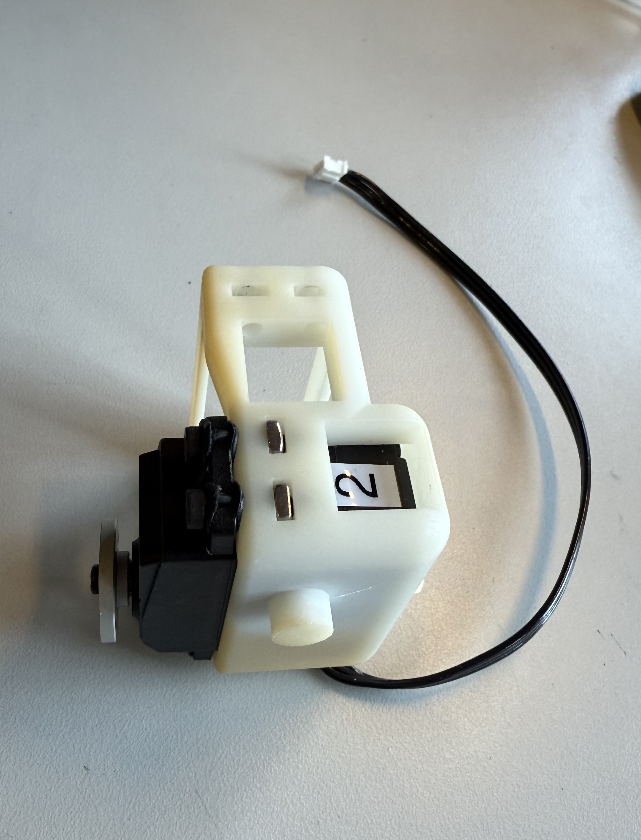
- Insert four of the M3 square nuts into the square nut slots around the motor and screw them down using the M3 x 16 mm screws.
- Attach a JST cable to bottom connection point of motor 2.
Neck Tilt
- Insert the black rubber spacers into all four of the screw slots on motor 1
-
Insert motor 1 into the remaining motor slot, making sure the servo horn and shaft are aligned to the plastic pin on the opposite side as shown below.
- Insert four of the M3 square nuts into the square nut slots around the motor and screw them down using the M3 x 16 mm screws.
- Attach JST cable from motor 2 to top connection point of motor 1.
- Attach additional JST cables to both sides of motor 1.
Head Assembly
The Head Assembly will require:
- a M3 hex screwdriver
- 8x silver servo horn M3 screws from the motor package
- 2x M3 x 20 mm screws
- 2x M3 square nuts
As recommended with every step, it is best to pre-thread the screw holes on the 3D printed parts.
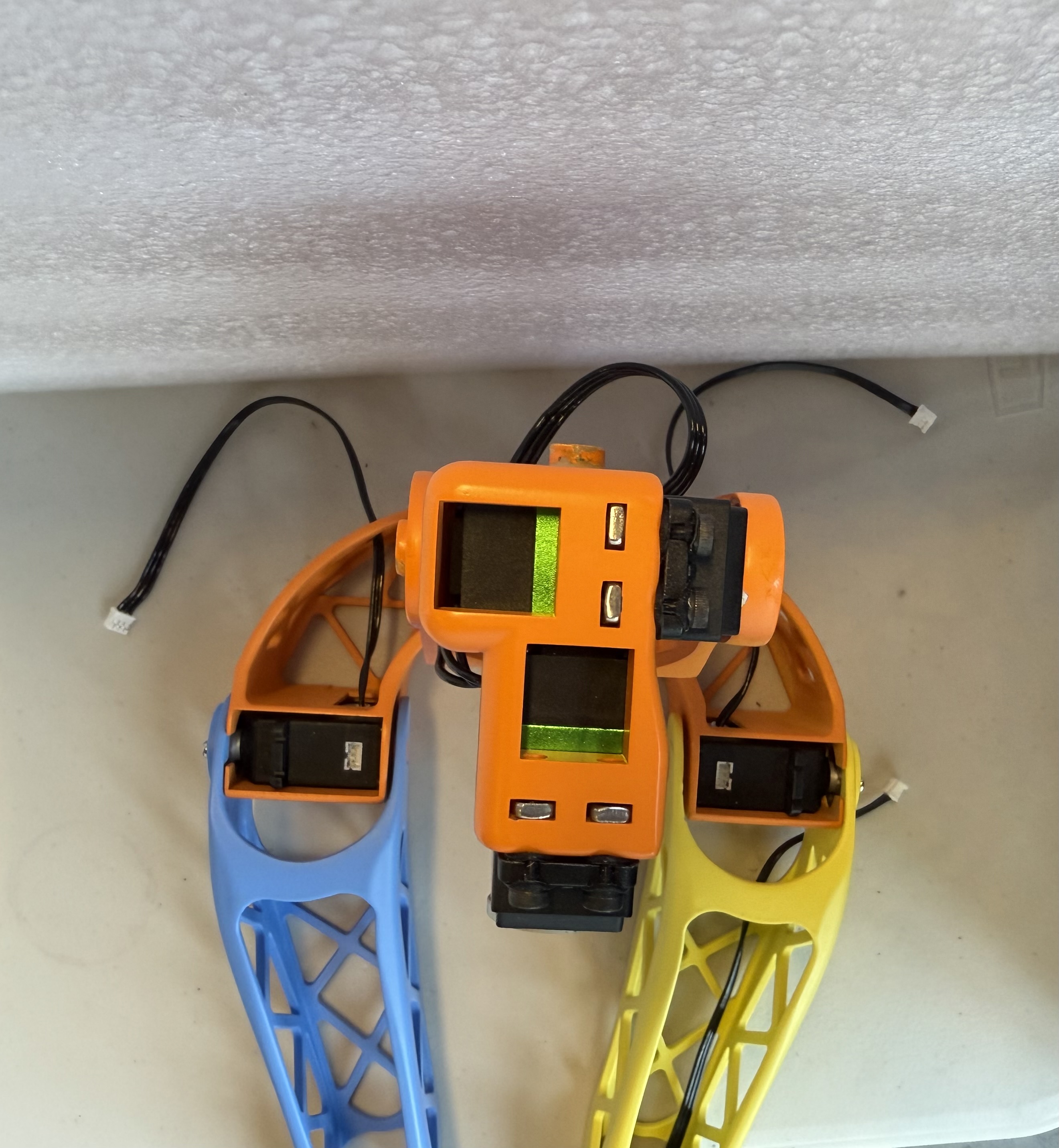
- Attach Neck Connector to motor 1 and secure with 4 silver M3 screws. Follow images below for correct orientation.
-
Attach U-shaped piece to motor 2 using 4 silver M3 screws.
-
Insert 2 square nuts into the slots on U-shaped piece. Use a small tool to push them as far in as they can go. LED panel can also be added at this step (press-fit attachment).
- Place headshell on top of U-shaped piece by aligning cylinder shaped press-fits.
-
Secure in headshell with 2 M3 x 20 mm screws.