Assembling the Arms and Hands
When assembling the arms for the robot, it is best to begin with the bicep, then shoulder, and ending with the forearms. This is due to the slight complexity behind the arm assembly. You will need to attach the motors and JST cables onto certain pieces before moving on.
The first step that is highly recommended is pre-setting all of the Arm motors before beginning the assembly.
The HiWonder HTS-20H servos involved in this assembly would be:
- Right Shoulder
- Right Bicep
- Right Elbow
- Left Shoulder
- Left Bicep
- Left Elbow
The forearms will require one Actuonix PQ12 Micro Linear Actuator each.
All correlated motor IDs are listed above in Initializing Servo IDs and Positions, as well as instructions for how to set the IDs and their home positions. It is also recommended that you check the servo horn orientation during this time, following the alignment found here Servo Horn Alignment.
Biceps
The biceps will require:
- a M3 hex screwdriver
- 2x servo horns
- 2x black M3 screws from the motor package
- 4x black rubber spacers from the motor package
- 4x JST cables
- 4x M3 x 18 mm tapered screws
- 4x M3 x 25 mm hex screws
- 4x M3 square nuts
- 4x M3 hex nuts
- Motor ID 10
- Motor ID 6
- Motor ID 7
- Motor ID 11
As recommended with every step within the assembly, it is best to pre-thread the screw holes on the 3D printed parts.
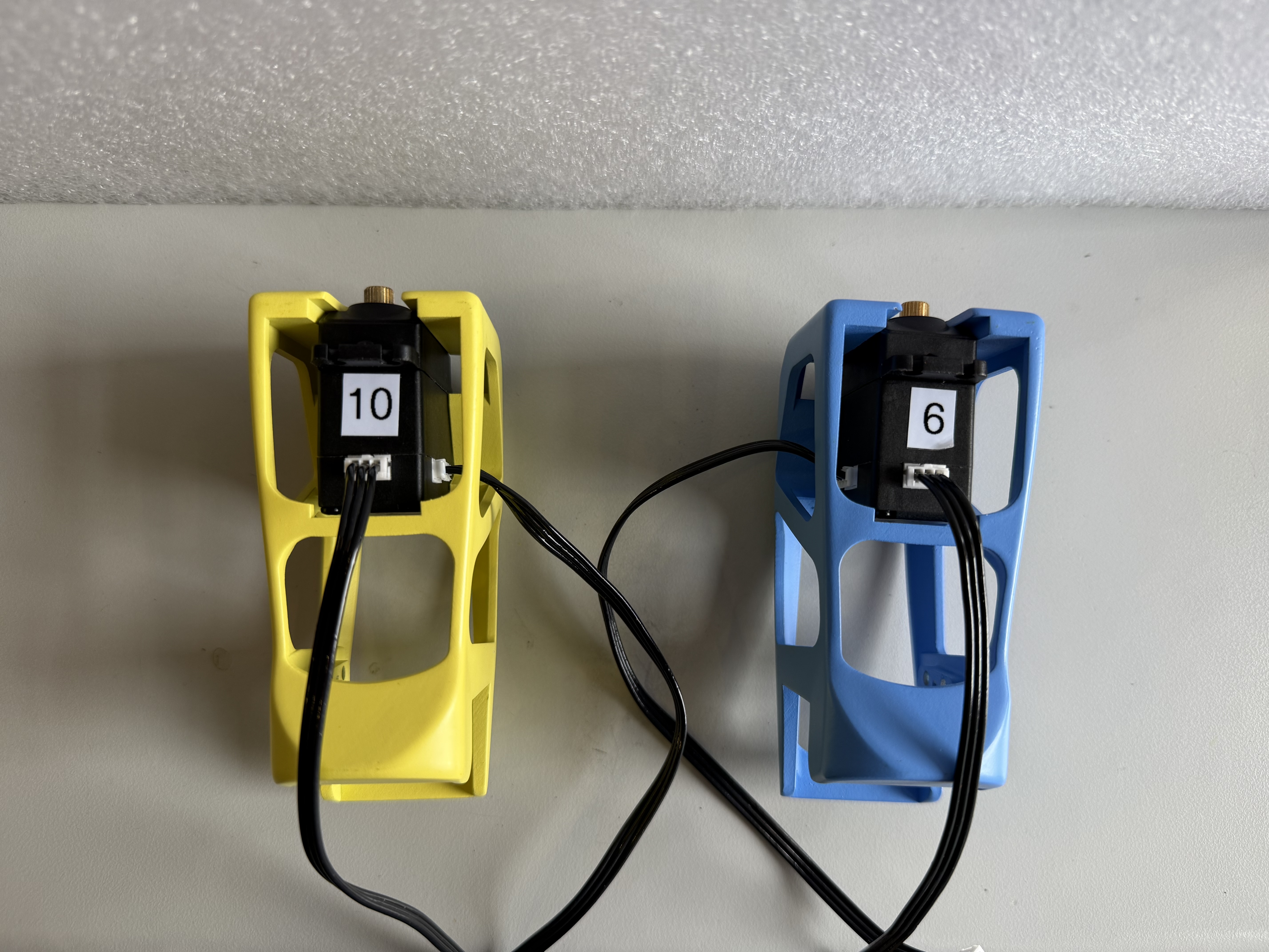
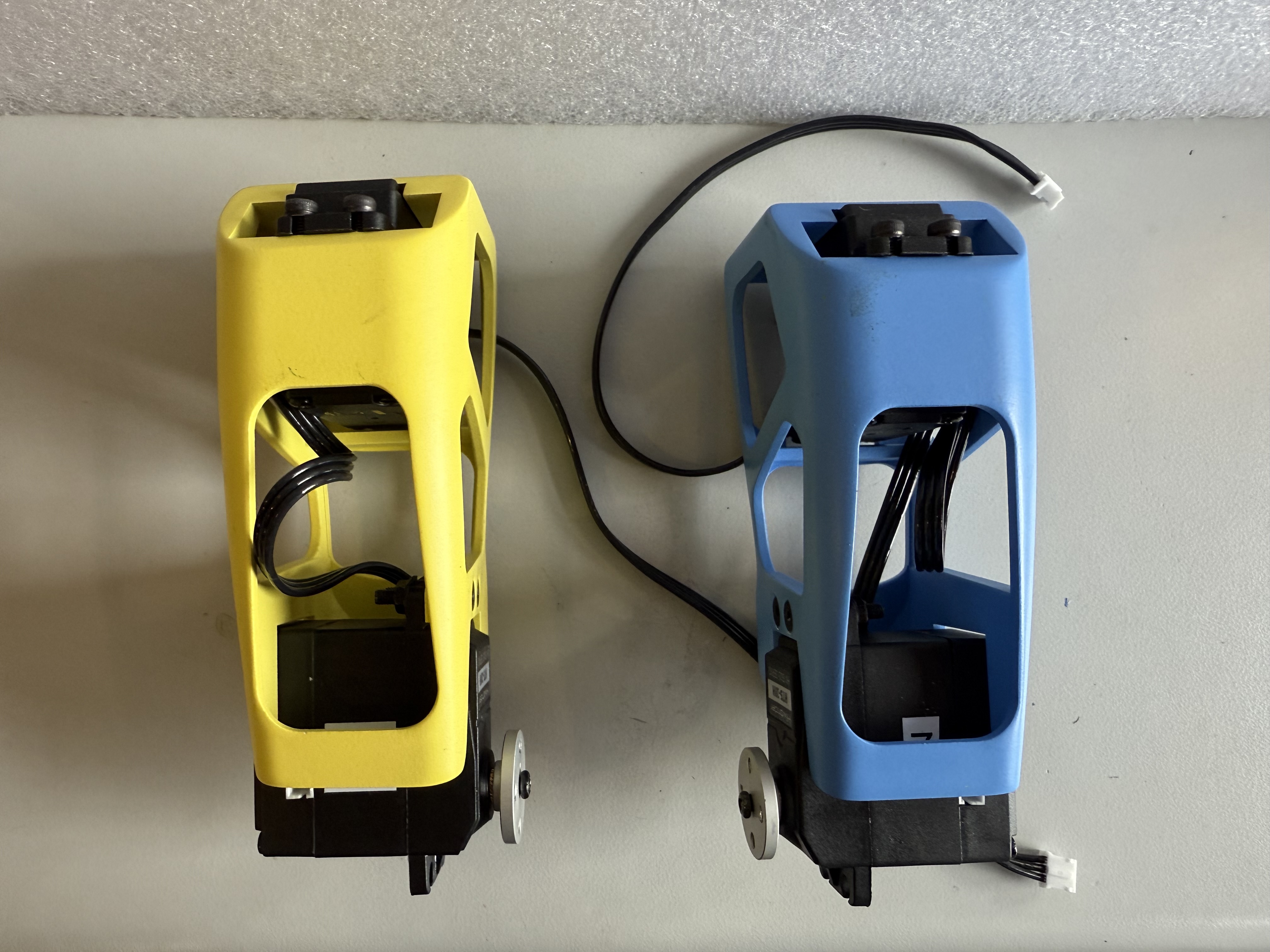
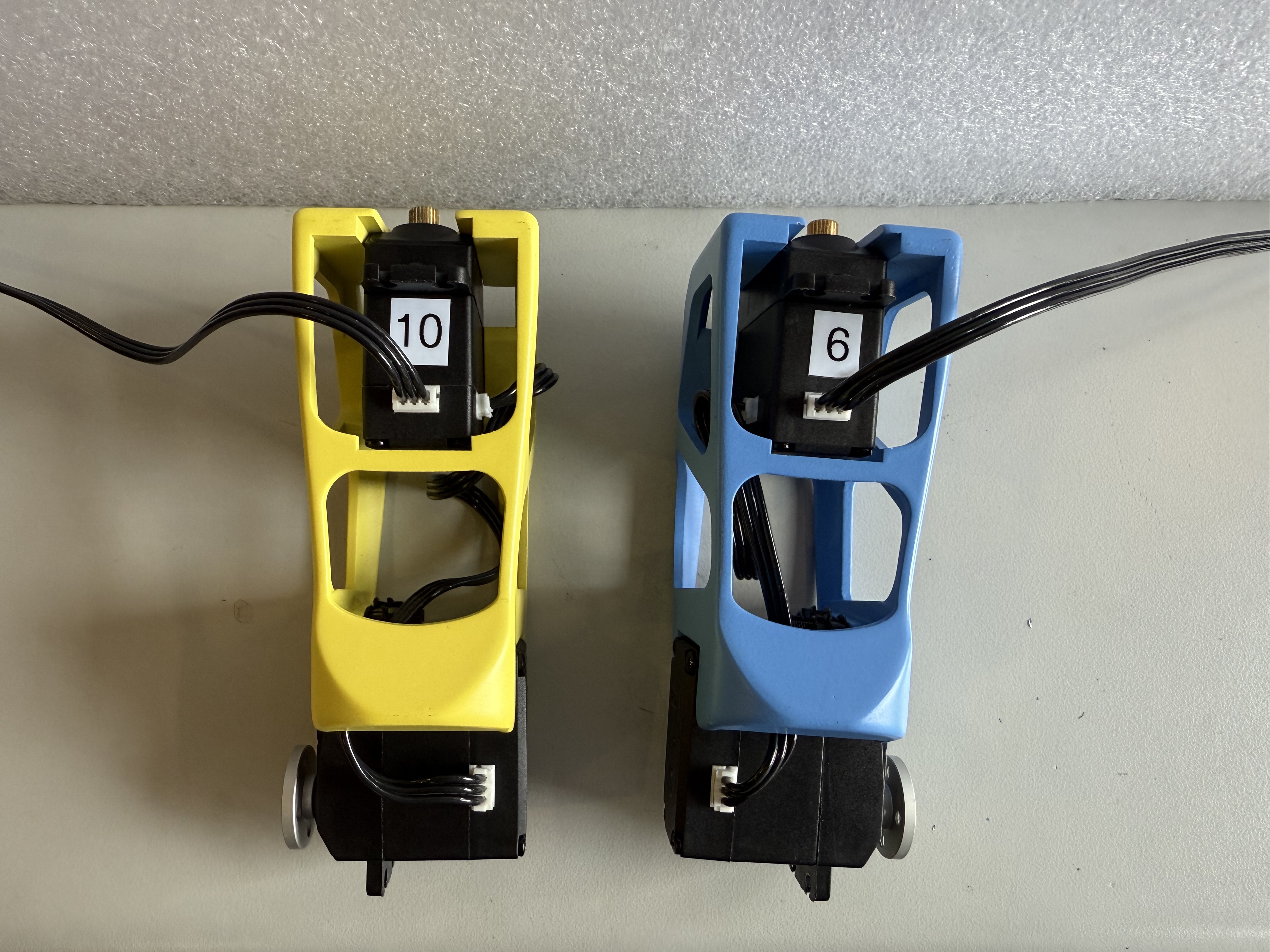
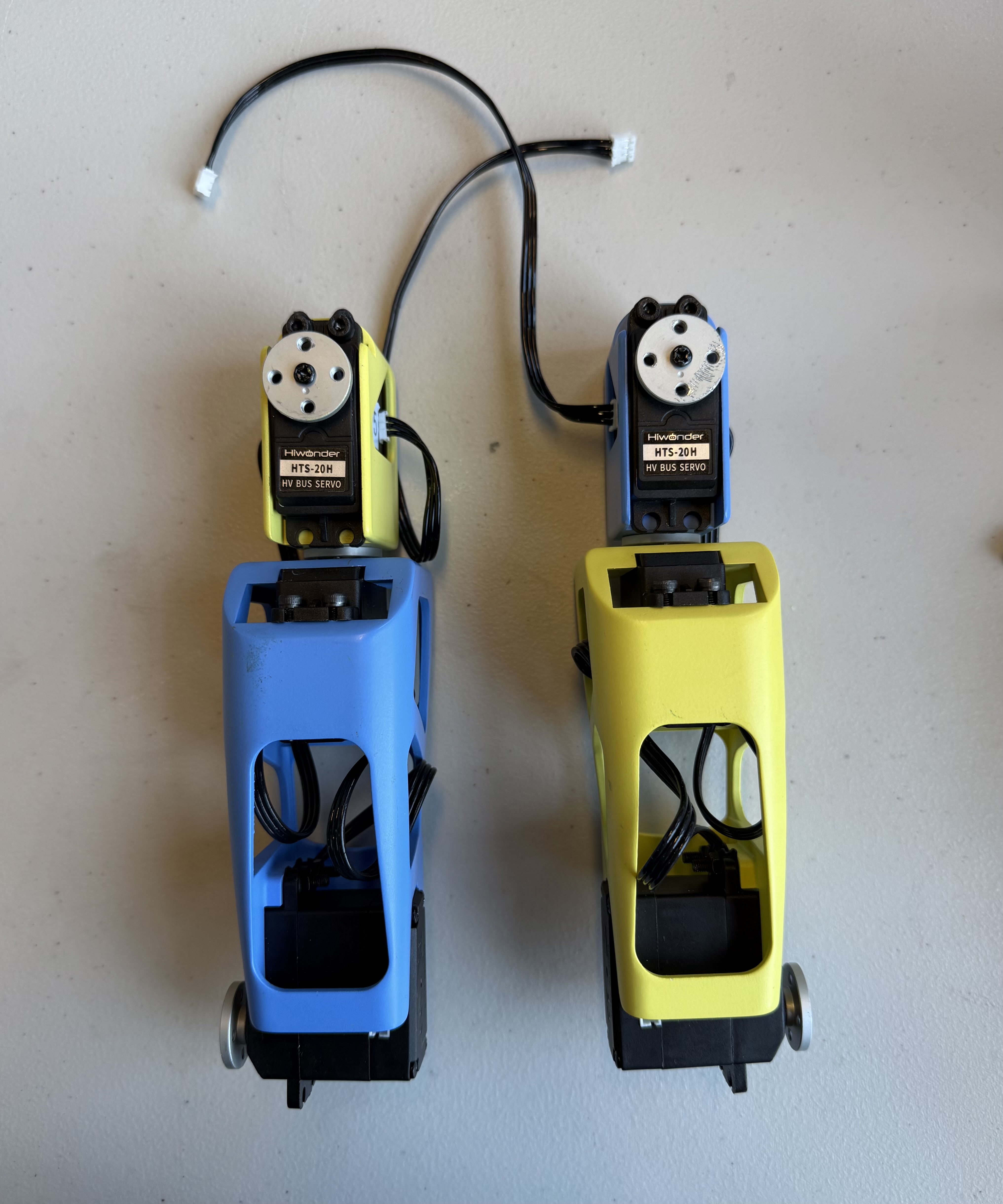
- Attach 2 JST cables onto the back and right side of motor 10, and 2 cables onto the back and left side of motor 6.
- Insert 4 square nuts into the slots located on the inside of the Biceps. Align them so you can’t see them from the top.
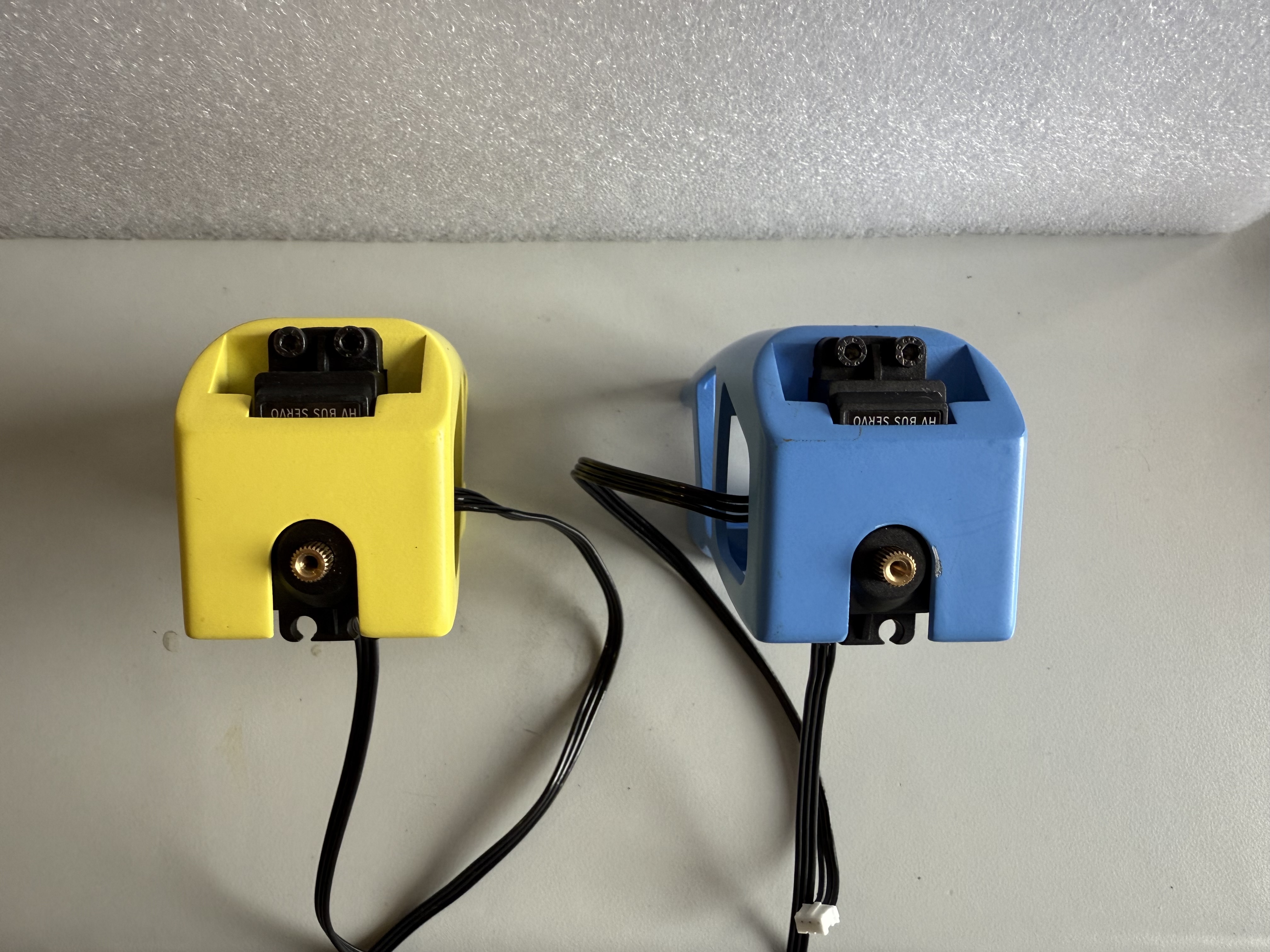
- Insert motors 10 and 6 into the Bicep pieces, secure them with 4 M3 x 25 mm screws.
Bicep references with JST cables:
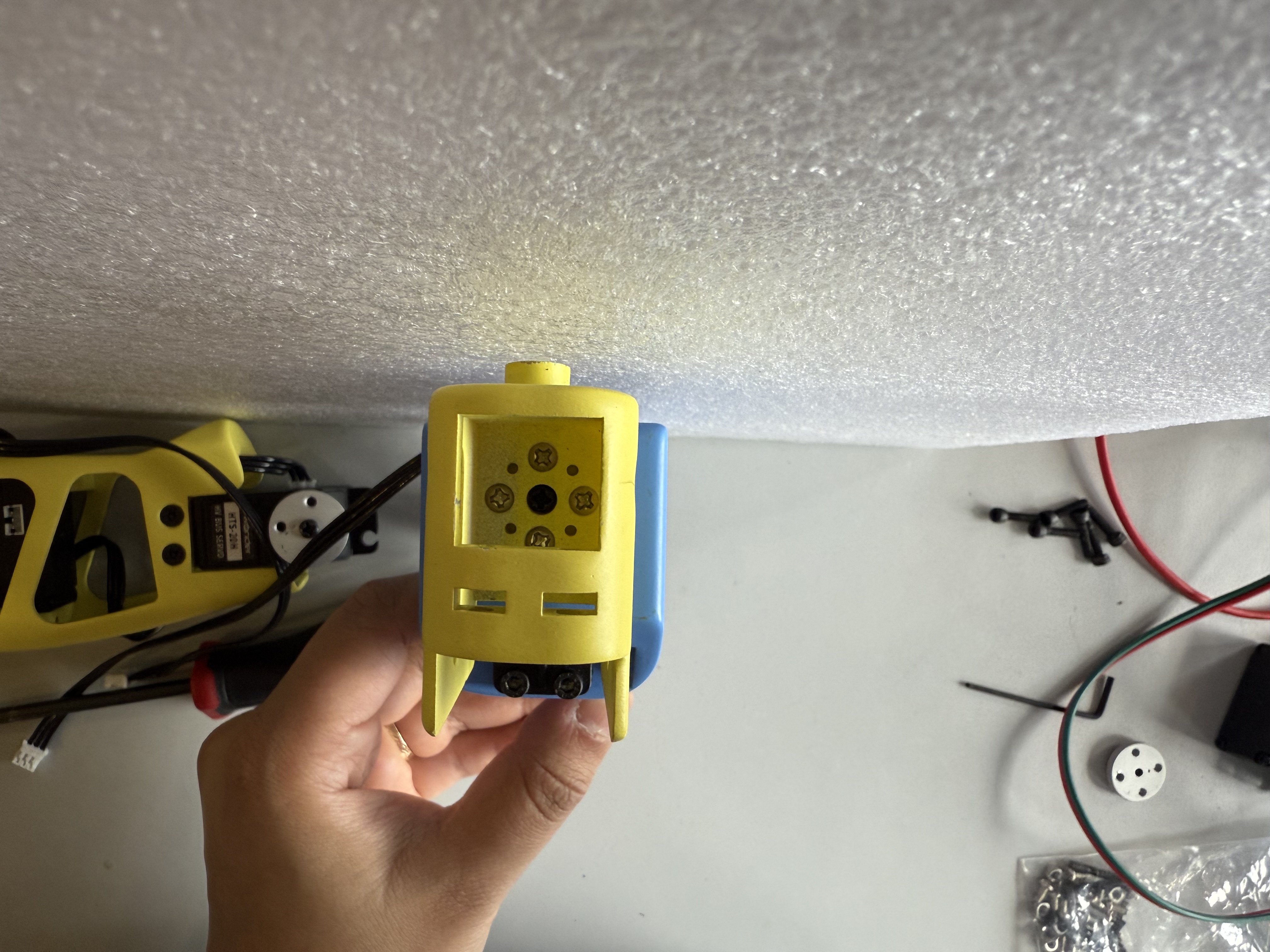
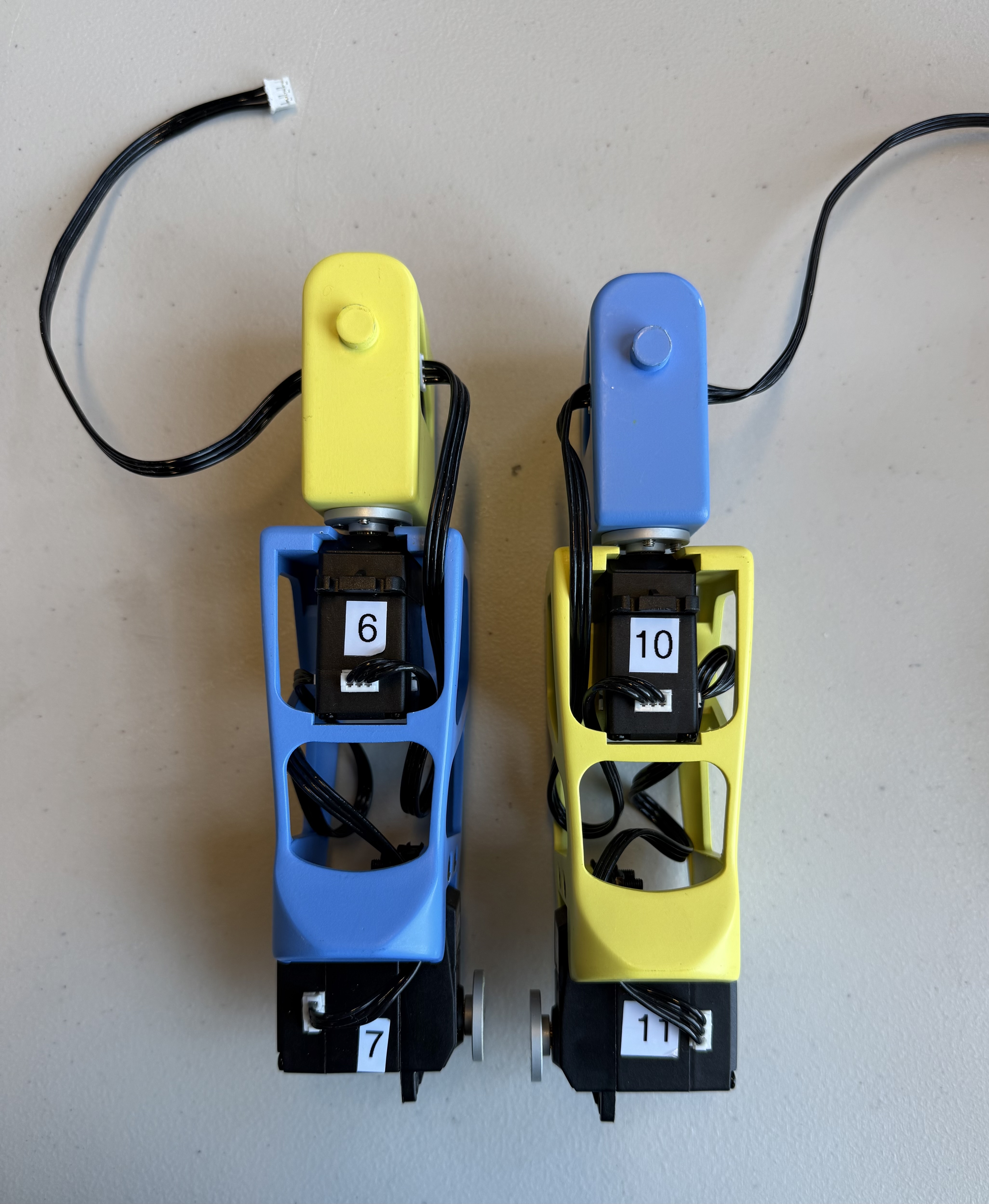
- Add 4 rubber spacers onto the top screw notches of motors 7 and 11.
- Attach the motors onto the lower placement of the Bicep pieces using 4 M3 x 18 mm tapered screws. Secure them with 4 M3 hex nuts.
- Connect the side JST cables of the upper motors to the back connection of the lower motors.
Final products (Right motor and Left motor):
Shoulders
The Shoulders will require:
- a M3 hex screwdriver
- 8x silver servo horn M3 screws
- 2x black M3 screws from the motor package
- 4x black rubber spacers from the motor package
- 4x JST cables
- 4x servo horns
- 4x M3 x 16 mm hex screws
- 4x M3 square nuts
- Motor ID 4
- Motor ID 9
As recommended with every step, it is best to pre-thread all screw holes. This is especially important for the Shoulders due to the uniqueness of its screw placements.
- Attach servo horns using 8 silver M3 screws onto the bottoms of the Shoulder pieces. Point the servo horn dimple toward the front of the piece.
Outcome of servo horn attachment:
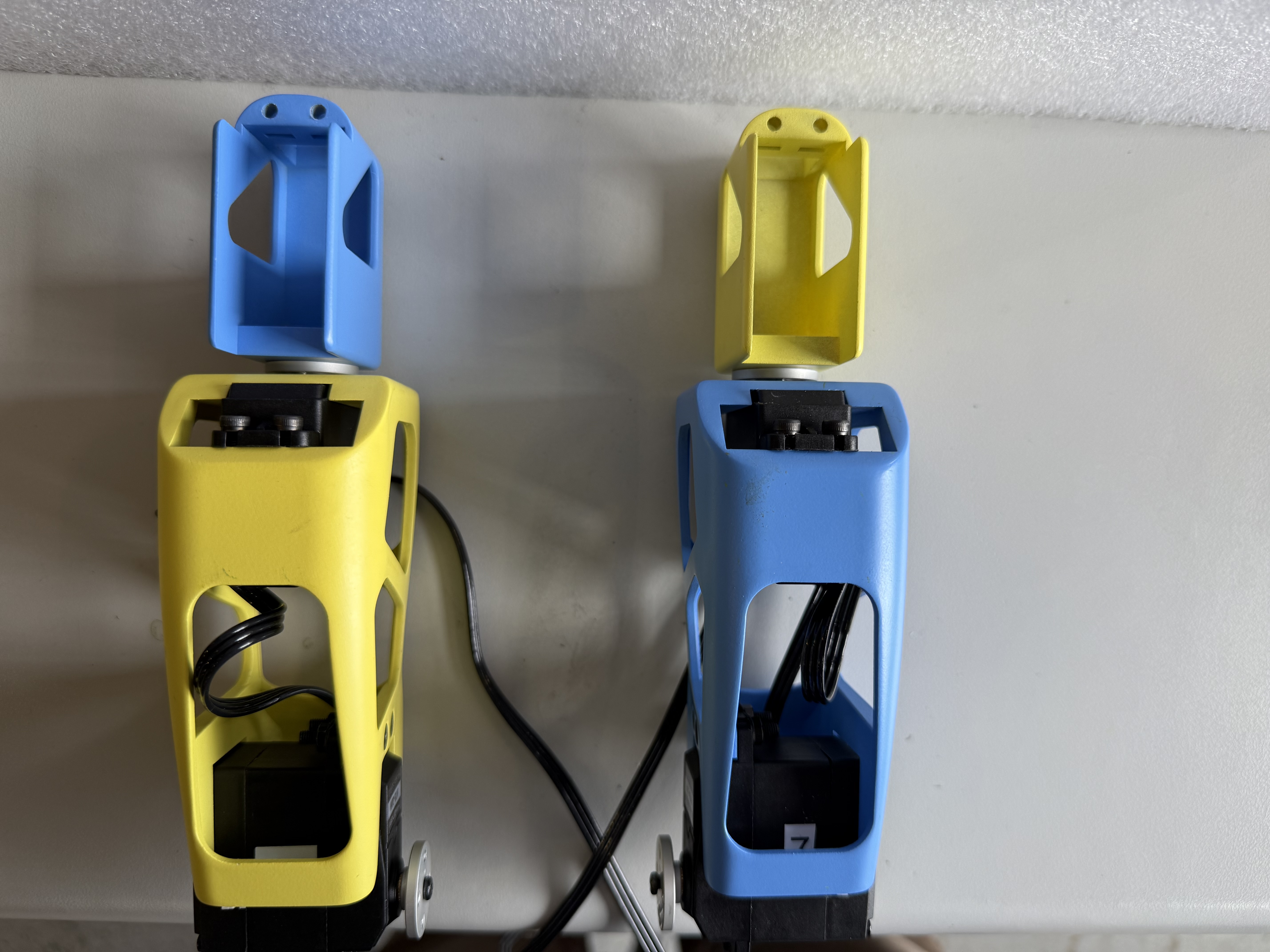
- Add 4 rubber spacers onto motors 5 and 9, only on the top screw notches.
- Insert motors 5 and 9 into the shoulders, screw them in place using 4 M3 x 14 mm hex screws and 4 M3 square nuts.
- Attach servo horns and JST cables from the back of the upper Bicep motors to the outer sides of the Shoulder motors. Right side for Right Shoulder, Left side for Left Shoulder.
- Attach 2 more JST cables to the inside of the Shoulder motors.
Final product:
Forearms
The Forearms will require:
- a M3 hex screwdriver
- 8x silver M3 screws
Pre-thread all screw holes before assembly.
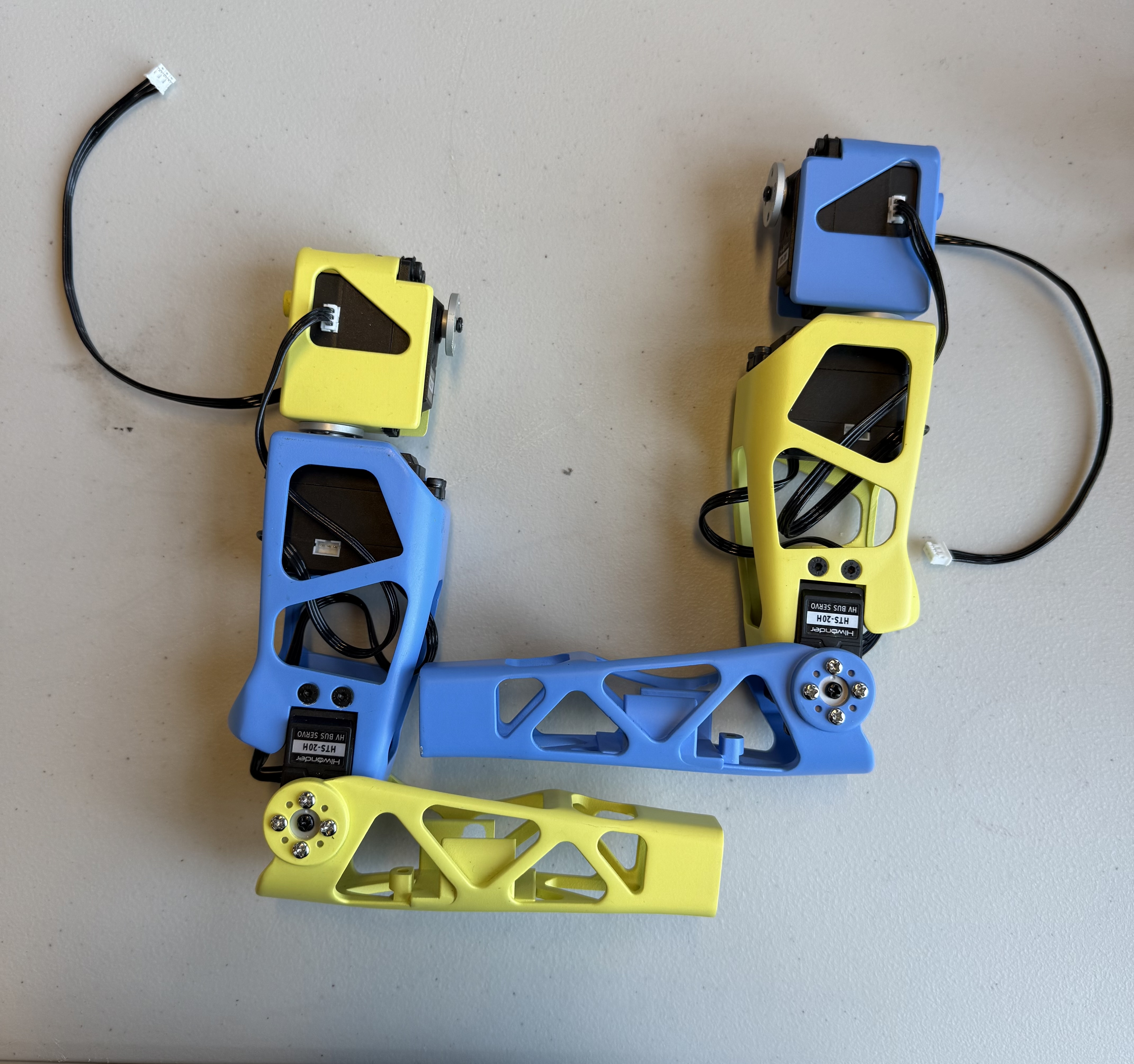
- Attach Forearms to respective Biceps using 4 silver M3 screws each.
Final assembly (ignore color differences, pieces were printed incorrectly):
Hands Construction & Assembly
Before beginning assembly, please be sure to double check that the hinges match the size-dependent and axial orientation on the fingers, with the fingers aligned to their corresponding palm (Figures 1-3). This assembly will require:
- TPU finger hinges
- Resin printed fingers
- 0.38 mm (0.015 in) fishing line
- 4 2.5 mm self-tapping screws (from the motor package)
- pair of thin nose pliers
- scissors
- small files
- 2 Actuonix PQ12 Micro Linear Actuators
- 2 U-shaped metal pieces (from linear actuator box)
- 2 M3 x 12 mm screws
- 2 lock nuts
- 2 square-shaped nuts
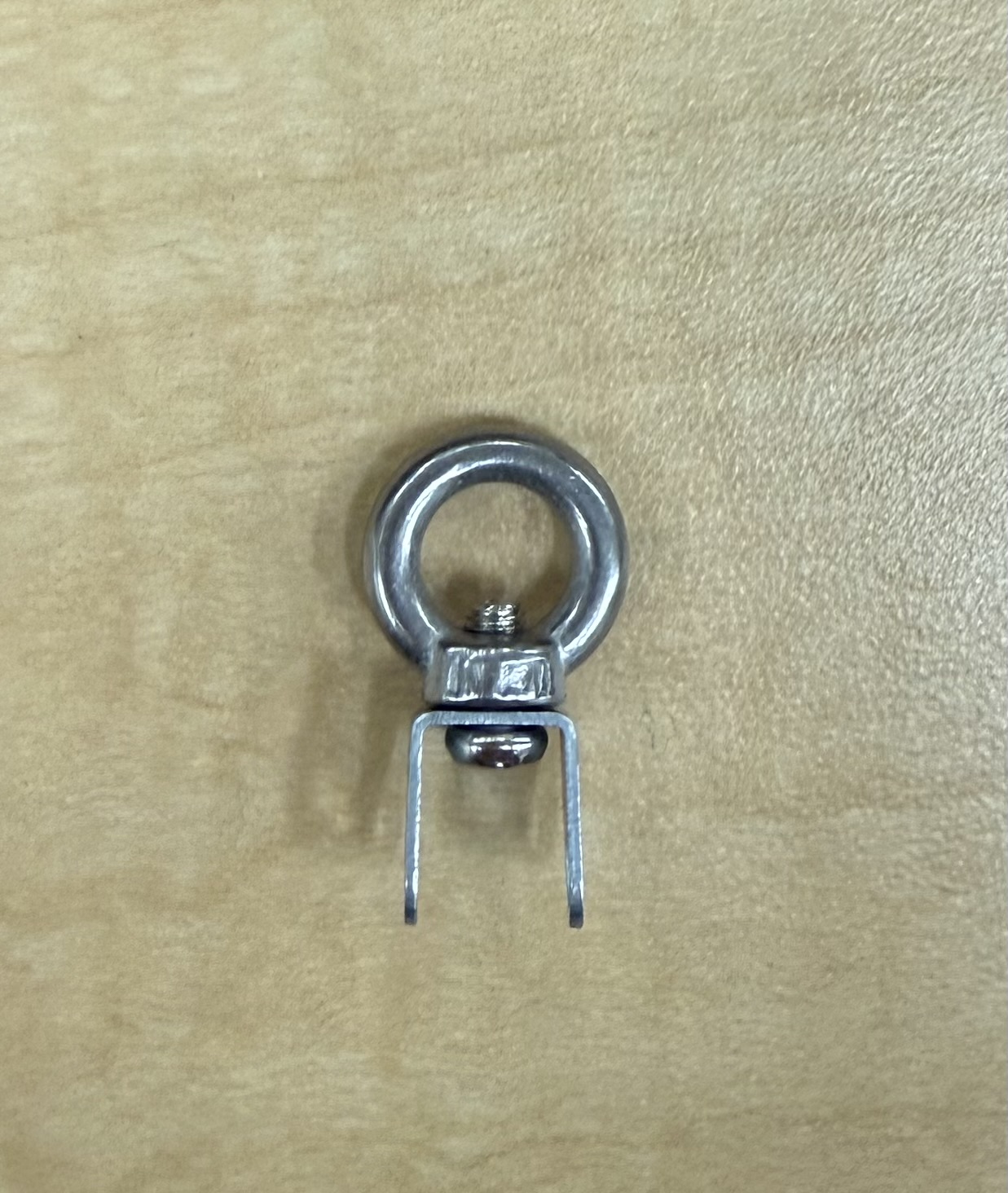
- 2 eyebolts
- 2 M3 small screws (from linear actuator box)
- 2 M3 medium length screws (from linear actuator box)
- Fit the largest hinges into the 4 largest slots on the palm using the side with the hole in it. The material is “spongey”, you can use pair of pliers to push it in. If necessary, shave the area use a small file or craft night.
- Fit two small hinges into the thumb slot using the same process mentioned in step 1. If necessary, shave the area use a small file or craft night.
- Slide first finger hinges in place following size constraints and hand orientation.
- Repeat process using smaller hinges and finger components, referencing the figures below as needed.
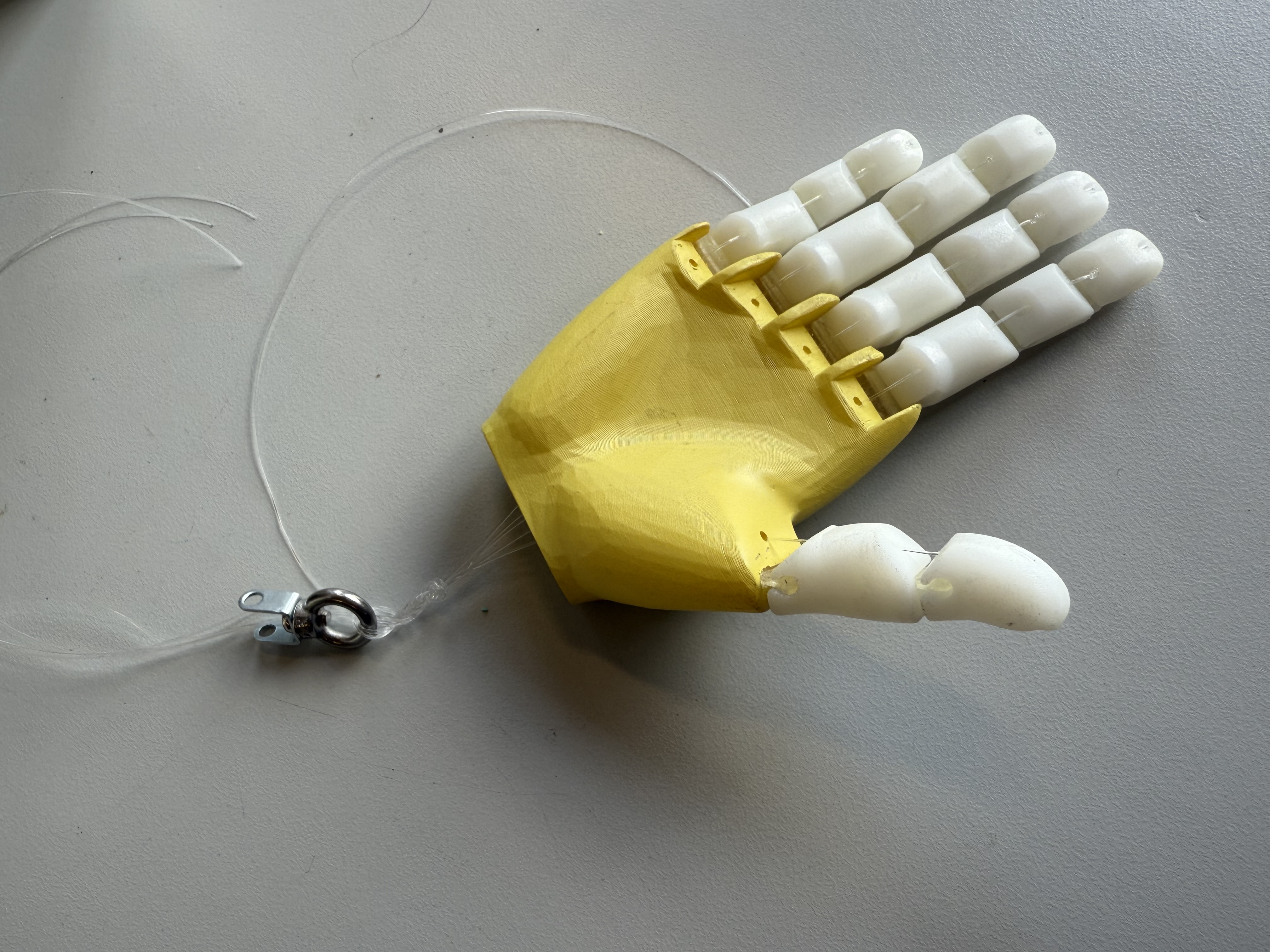
- Cut ~30 mm of fishing line per finger, ~25 mm for the thumb.
- Fit fishing line through the bottom of the heand up through one set of finger components.
- Restring fishing line back through the top finger component. Leave enough room to tie off later.
- Ensure that the length is adequate enough to later attach to the forearm. If so, tie off the top of the finger using pliers to get a tight knot (may need to make more than one knot). Use Figure 4 as a reference.
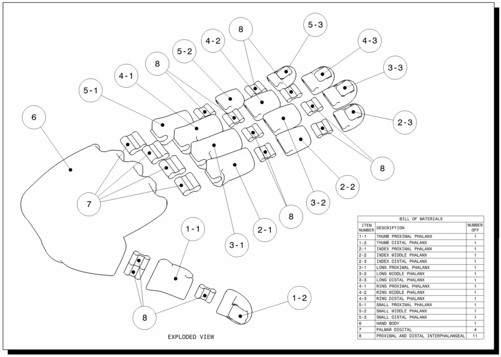
Figure 1: Composition and BOM of Flexy-Hand 2 (Flexy-Hand 2)
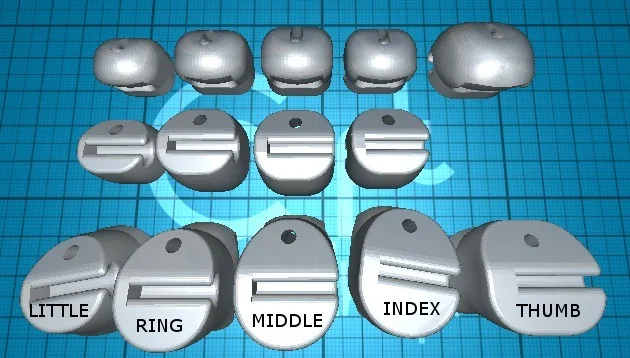
Figure 2: Finger plate with labeled orientation (Flexy-Hand 2)
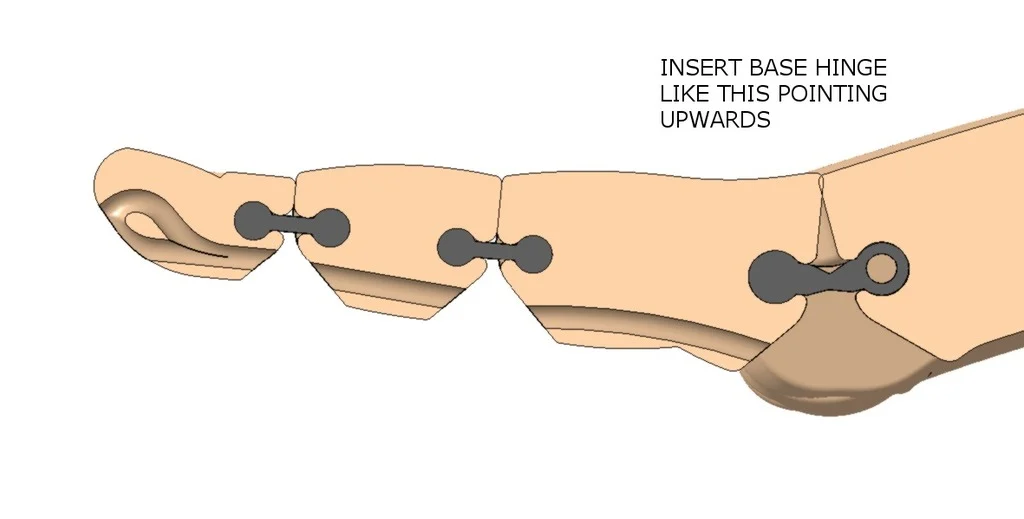
Figure 3: Hinge orientation for all fingers (Flexy-Hand 2)
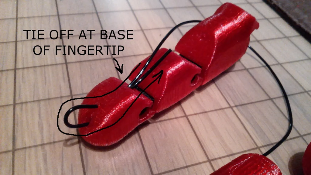
Figure 4: Tendon knot placement for all fingers (Flexy-Hand 2)
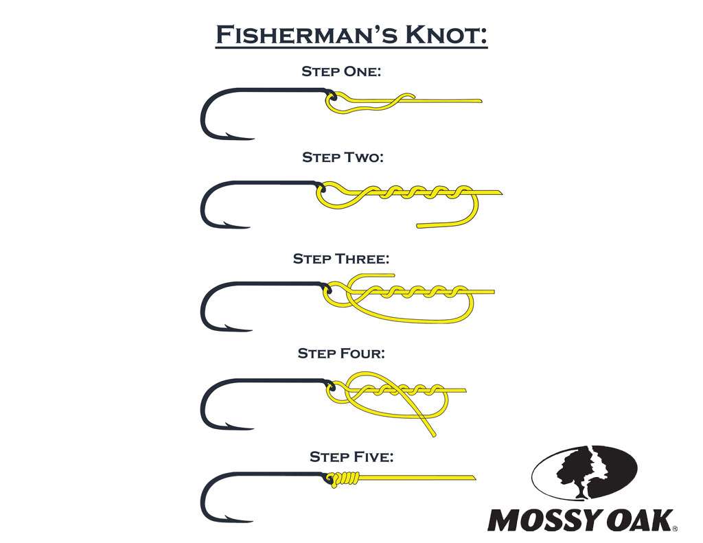
Figure 5: Fisherman’s Knot instructional image
Continued…
-
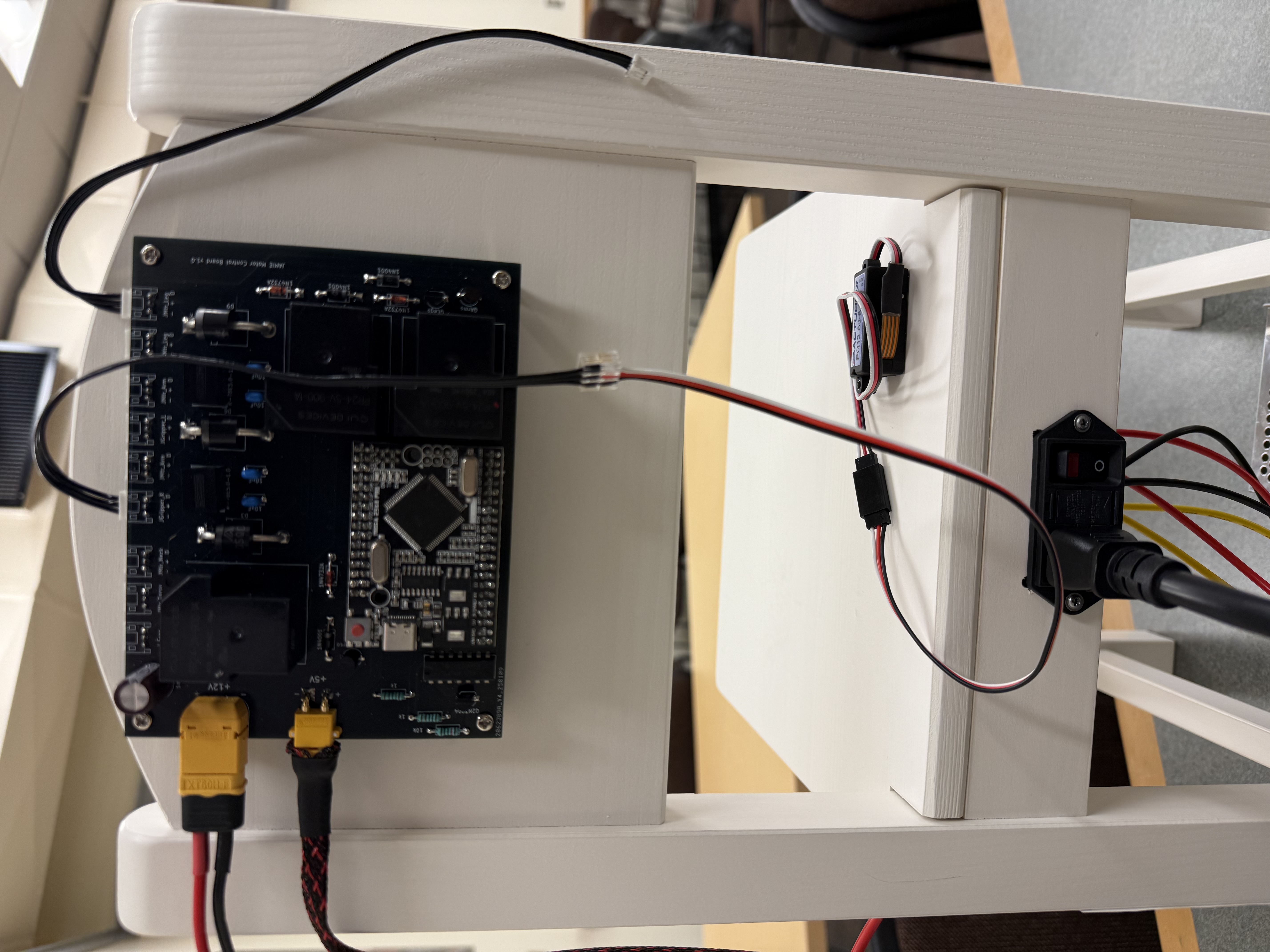
Set up linear actuators to board and move them to max length before assembly. Follow Arduino code provided in LinearActuatorSet.
-
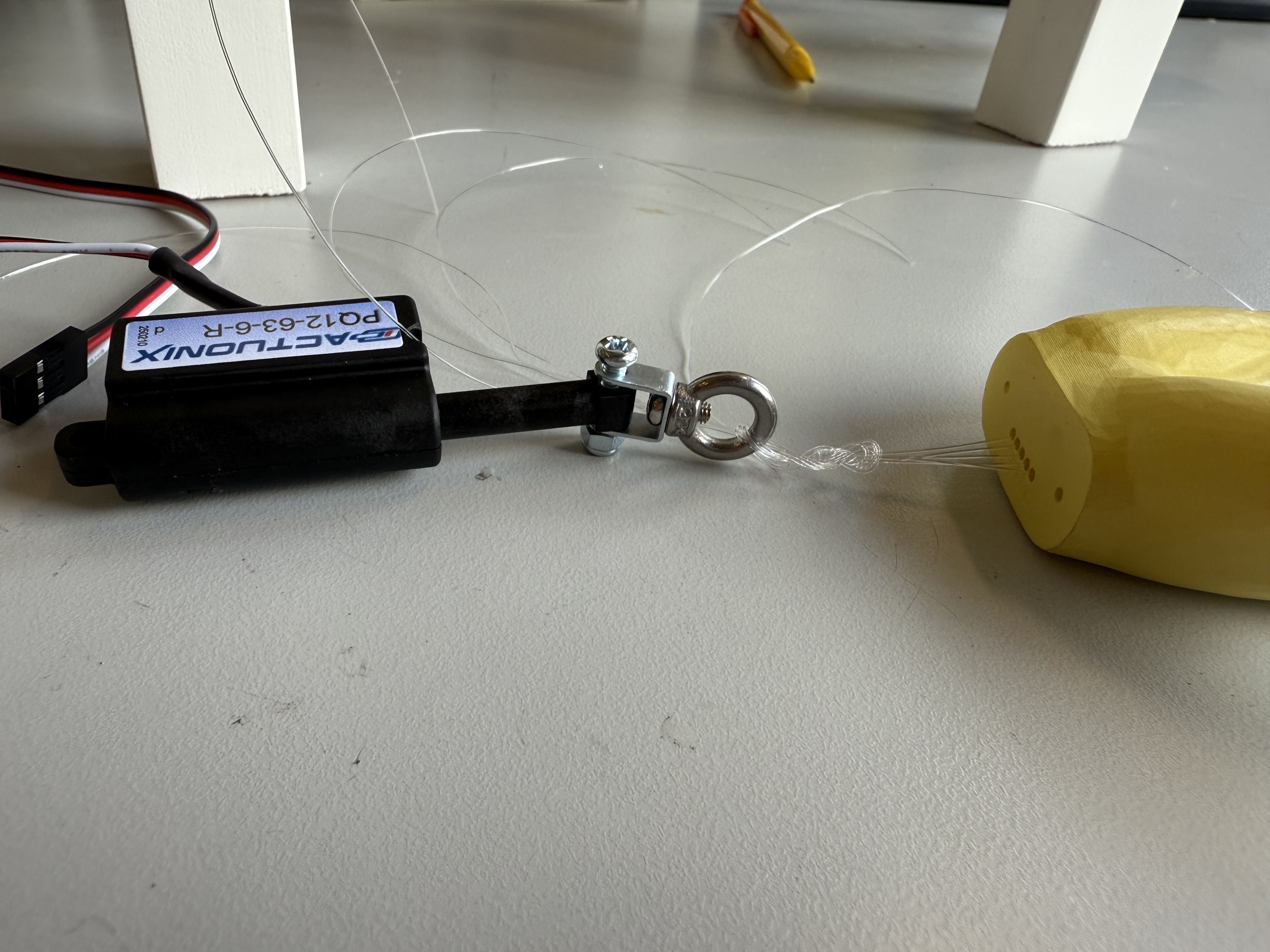
Attach eyebolts to middle screw hole of U-shaped metal piece using the smallest M3 screws from the linear actuator package.
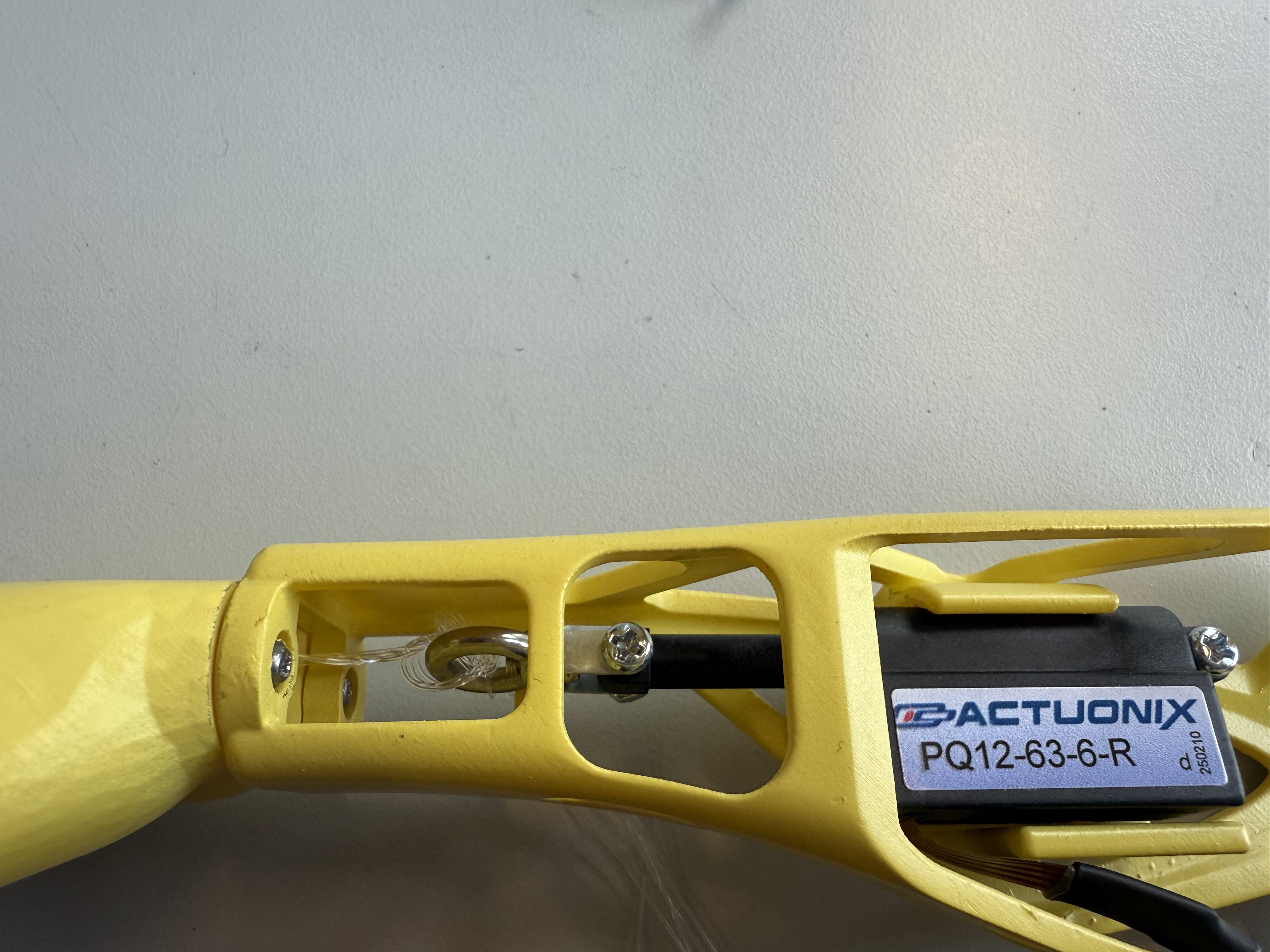
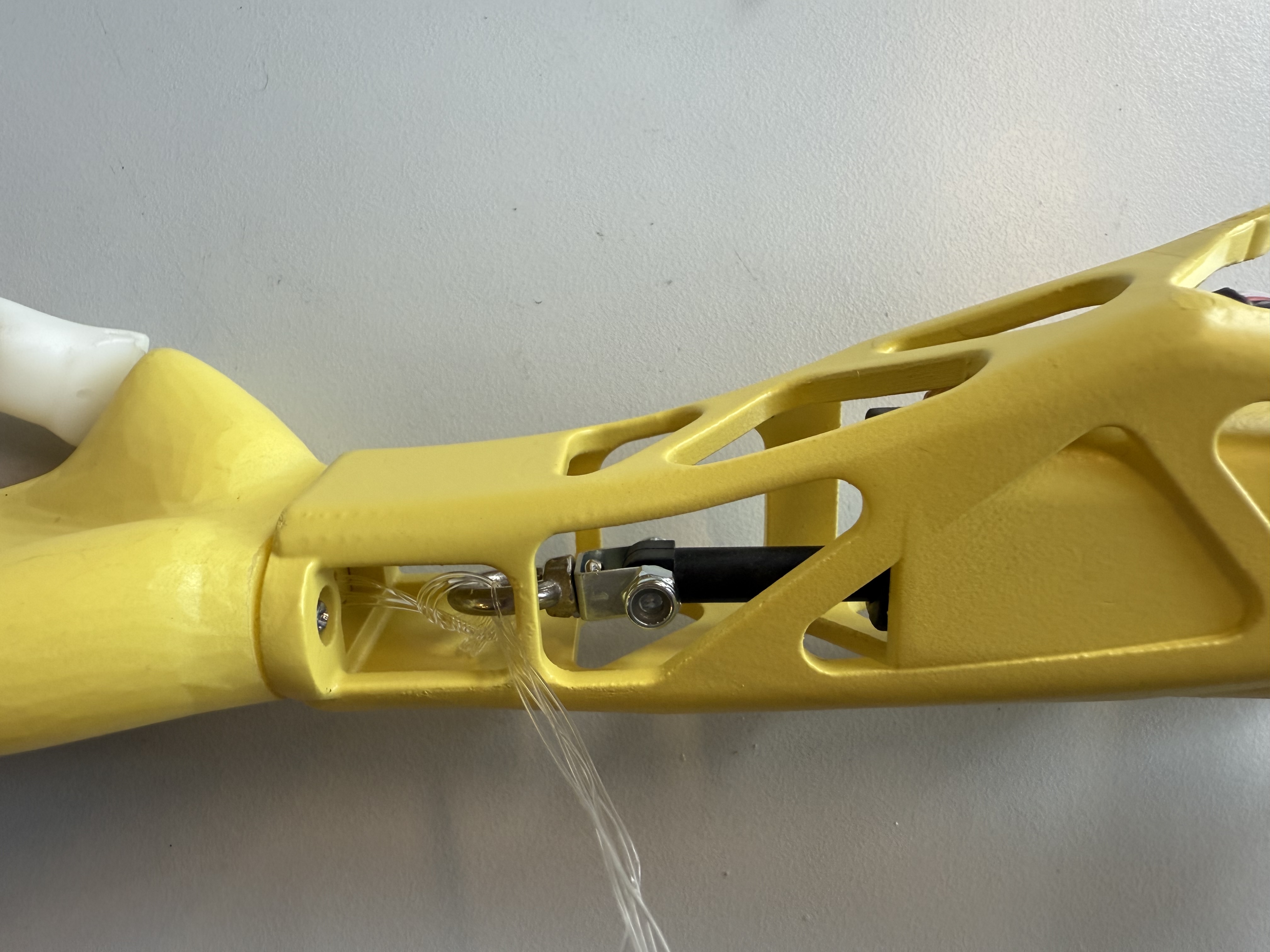
- Attach linear actuators to Forearm piece using M3 x 12 mm screws and square nuts (see Final product reference).
- Tie all 5 fishing lines to eyebolt using a ‘Fisherman’s Knot’. Use Figure 5 as a reference.
- Attach hands to the forearms using the 2.5 mm self-tapping screws.
- Attach other 2 screw holes of U-shaped metal piece to linear actuator using the medium length M3 screws and lock nuts. Note: This image is only meant to show how linear actuator and hand should be attached. Only attach the two once the linear actuator is screwed into the forearm.
Final product (Right Arm):