
Initializing Servo IDs and Positions
** If you received a kit, the servo IDs and initial positions have already been set! Please skip this step! **
** There is currently an error between the motor control board and the individual motors where if there is only one motor connected, it may burn out when it tries to run. Try not to run the motors from the board unless they are all connected. **
You will need to communicate with the motors as part of the assembly process. This process can be completed using the assembled motor control PCB, or the HiWonder motor debugging board.
In either case, you will be initializing each motor by connecting and communicating with it individually (not chaining the motors). The below initialization instructions assume you are initializing the motors using the robot motor control PCB.
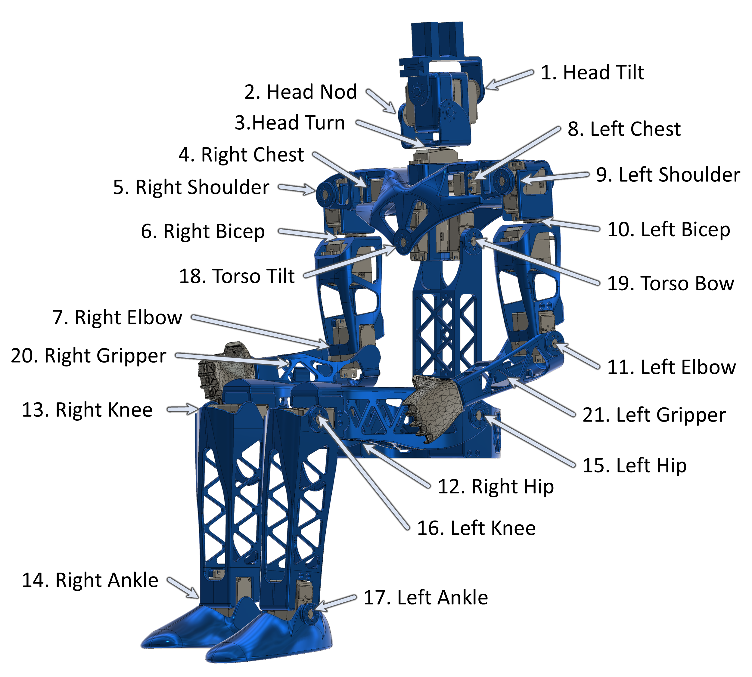
Before assembling the robot, it is necessary to assign unique motor IDs for each joint motor. You can set these IDs with the SetServoID Arduino code project using the motor control PCB for the robot. Any ID numbers may be chosen, but the default configuration file, and these assembly instructions, will use the joint names and IDs as listed in the table below.
| Joint Name | ID | Assembly Pose (Angle) |
|---|---|---|
| Head Tilt | 01 | 125 |
| Head Nod | 02 | 125 |
| Head Turn | 03 | 120 |
| Right Chest | 04 | 135 |
| Right Shoulder | 05 | 85 |
| Right Bicep | 06 | 115 |
| Right Elbow | 07 | 90 |
| Left Chest | 08 | 115 |
| Left Shoulder | 09 | 180 |
| Left Bicep | 10 | 115 |
| Left Elbow | 11 | 105 |
| Right Hip | 12 | 84 |
| Right Knee | 13 | 90 |
| Right Ankle | 14 | 80 |
| Left Hip | 15 | 96 |
| Left Knee | 16 | 80 |
| Left Ankle | 17 | 90 |
| Torso Tilt | 18 | 115 |
| Torso Bow | 19 | 125 |
| Right Gripper | 20 | 0 |
| Left Gripper | 21 | 0 |
During assembly of the robot, it will be necessary to set each motor to a known rotation and then assemble the parts to match that orientation. These positions are not operational home, but are instead an easy reference position for use in assembly. The robot assembly pose, along with each joint name, motor ID, and the motor angle corresponding to the current pose, are shown in the image below.
To simplify assembly, the initialization steps for each motor are:
- Connect to board “Arduino Mega or Mega 2560” on Arduino IDE.
- Set the motor ID of the servo with the SetServoID Arduino code project. Change the code to the motor ID you want to set.
- Set the motor to it’s assembly home position using the SetServoPosition Arduino code project. Change the code so that you are only running 1 motor (the ID you just set) and 1 angle (the home angle you want to set).
-
While the servo is in the home position, attach the servo horn such that the dimple on the horn is facing towards the servo body as shown below.
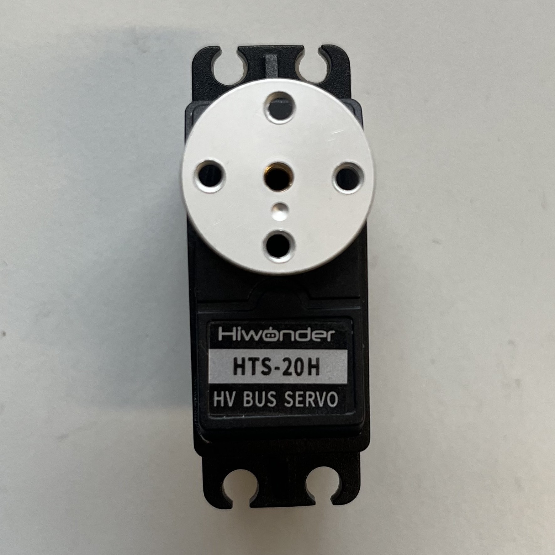
- Cut power to the servo and screw down the aligned horn using the black center screw from the servo accessory bag.