Cable Fabrication
There are three power cables that need to be assembled to supply power to the robot. Along with the power cables are two cables for the eyes, two cables for the hands, and two cables for the hips. The list of cables are shown below, and the components and assembly instructions for each are provided in this section.
- 1x PCB to 12V Power Supply Cable
- 1x PCB to 5V Power Supply Cable
- 3x 12V Power Supply to Outlet to 5V Power Supply Cable
- 1x Eye Panel Long Cable
- 1x Eye Panel Short Cable
- 2x Gripper Cable
- 2x Hip Motor to Control PCB JST Cable
For the fork connectors we used 14-16 gauge, #8 fork connectors with heat shrink attached, from wirefy and for the spade connectors, we used 10-12 guage, female quick disconnect spade connectors with heat shrink, also from wirefy.
12V PCB to Power Supply
This cable assembly connects the 12V power on the motor control PCB to the 12V power supply for the robot.
Materials
- 1x red 14AWG braided wire, 18” length minimum
- 2x red heat shrink pieces
- 1x black 14AWG braided wire, 18” length minimum
- 2x black heat shrink pieces
- 1x XT-60 female plug
- 2x fork connector #8, 16-14 gauge opening
Assembly
For connecting the wires to the XT-60 connector, you may follow this short video tutorial.
5V PCB to Power Supply
This cable assembly connects the 5V power on the motor control PCB to the 5V power supply for the robot.
Materials
- 1x red 18AWG braided wire, 24” length minimum
- 2x red heat shrink pieces
- 1x black 18AWG braided wire, 24” length minimum
- 2x black heat shrink pieces
- 1x XT-30 female plug
- 2x fork connector #8, 22-16 gauge opening
Assembly
12V Power Supply to Outlet to 5V Power Supply
This cable assembly connects both the 12V power supply and 5V power supply to the power outlet on the back of the chair that takes 120VAC wall power. The 12V supply and 5V supply are at different locations and could use different cable lengths, but for ease of assembly, we use the same lengths of wire for both of them.
Materials
- 2x red 14AWG braided wire, 12” length minimum
- 3x red heat shrink pieces
- 2x black 14AWG braided wire, 12” length minimum
- 3x black heat shrink pieces
- 2x yellow 14AWG braided wire, 12” length minimum
- 3x yellow heat shrink pieces
- 6x fork connector #8, 16-14 gauge opening
- 3x female spade connector, 12-10 gauge opening
Assembly
Eye Panel Long Cable
This is the logn cable connecting the first LED array panel to the motor control board.
You will need:
- 1x 3pin JST XH2.54 connector
- 1x 3pin JST PH2.0 connector
- 1x 3 wire cable, 16” length minimum
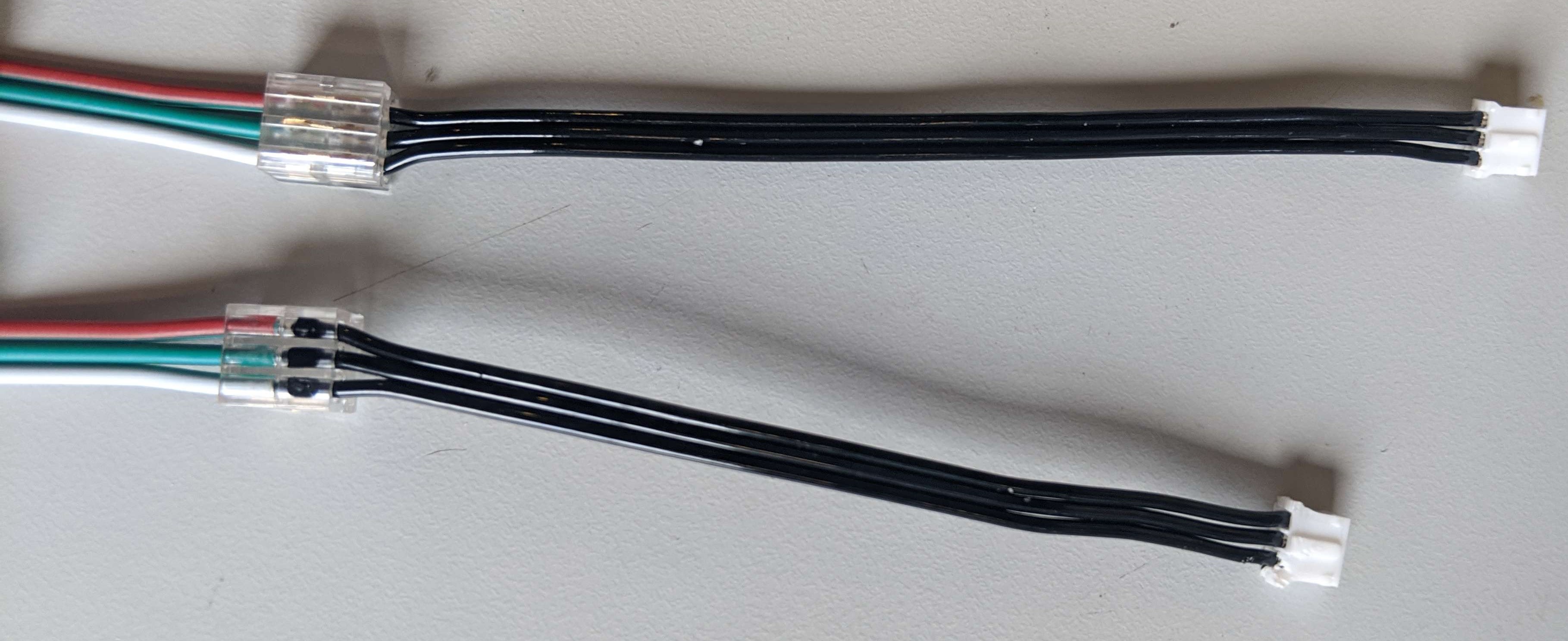
Assemble the cable so that wires connect into the connectors as shown in the image below.
Eye Panel Short Cable
This is the short cable combining the two LED array panels for the eyes.
You will need:
- 2x 3pin JST XH2.54 connectors
- 1x 3 wire cable, 4” length (try not to go long)
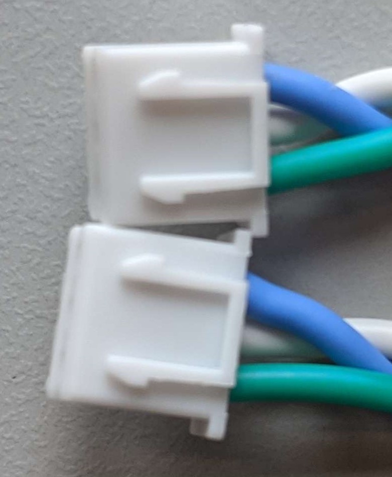
Assemble the connectors to the cable such that the connectors match each other (not mirrored!). See the photo below.
Gripper Cable
The cable to connector the gripper servo motors to the motor control pcb. It converts a dupont connector to a JST PH2.0.
You will need:
- 1x 3pin JST PH2.0 connector
- 1x 3pin Dupont female connector
- 1x 3 wire cable, ?? length minimum
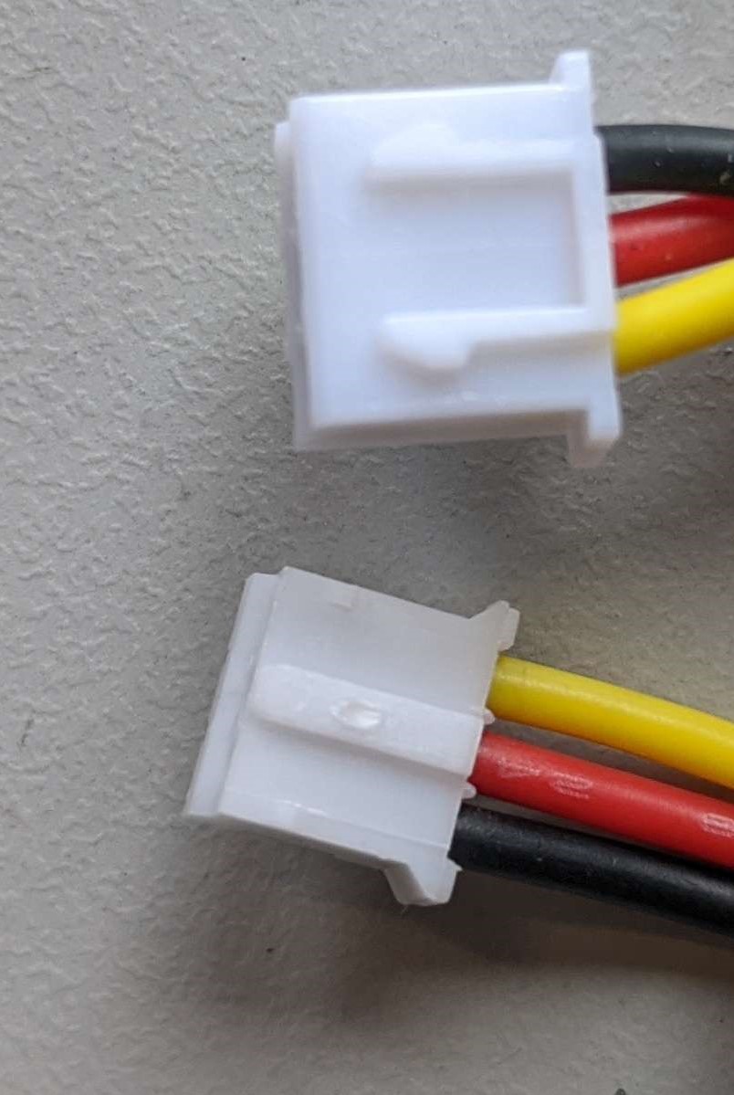
Connect the dupont to the jst as shown below, where white is the signal line, red is power, and black is ground.
Hip Motor to Control PCB JST Cable
For the two motors in the hips, the JST cables that come with the motors will need to be lengthened to reach the motor pcb. You’ll need to splice in a 12” length of wire. This can be done by soldering, or with mechanical splice connectors such as these.
You will need:
- 1x 3 pin JST cable (comes with motor)
- 1x 3 wire cable, 12” length minimum
- Solder and heat shrink or 2x mechanical crimp splicers.
Split the JST cable that comes with the motor down the middle. Then splice in the 12” length of cable, such that the connector ends match each other (not mirrored!) See the photo below.